Ventilation system and method of controlling the same

Inactive Publication Date: 2007-06-28
LG ELECTRONICS INC
View PDF16 Cites 9 Cited by
  • Summary
  • Abstract
  • Description
  • Claims
  • Application Information

AI Technical Summary

Benefits of technology

[0014] An object of the present invention is to provide a ventilation system that can simultaneously perform the illumination and the ventilation and can be easily installed with less installation space.
[0016] Still another object of the present invention is to provide a ventilation system that uses a solar cell as a sub-power source, thereby reducing a power consumption.
[0022] According to the present invention, since a ventilation system simultaneously performs the illumination and the ventilation, it can be easily installed with less installation space.
[0023] In addition, since the ventilation system uses a solar cell as a sub-power source of an artificial lightening and a sub-power source of thereof, power consumption can be reduced.

Problems solved by technology

However, the lightening system and the ventilation system have the following problems.
Since a space for the lightening system and a space for the ventilation system are required in an indoor space, they take up much indoor space.
In addition, a variety of wires for the systems are complicatedly arranged.
When the optical pipe is applied to the lightening system, the optical pipe and the duct are independently arranged on the ceiling, their installing space increases and the installing process is complicated.
However, when the proper locations conflict with each other, it cannot help deteriorating one of them.
Since the optical pipe or the duct is inevitably bent due to the arrangement design, the total reflection efficiency of the optical pipe may be deteriorated or the inner flow resistance of the duct increases.
Since the conventional optical pipe illuminates the indoor space using the separate lamp, the lamp must be always operated to illuminate the indoor space regardless of the outdoor weather and thus the power consumption increases.

Method used


Image

  • Ventilation system and method of controlling the same
  • Ventilation system and method of controlling the same
  • Ventilation system and method of controlling the same

Examples


Embodiment Construction

[0032] Reference will now be made in detail to the preferred embodiments of the present invention, examples of which are illustrated in the accompanying drawings. The invention may, however, be embodied in many different forms and should not be construed as being limited to the embodiments set forth herein; rather, these embodiments are provided so that this disclosure will be thorough and complete, and will fully convey the concept of the invention to those skilled in the art.

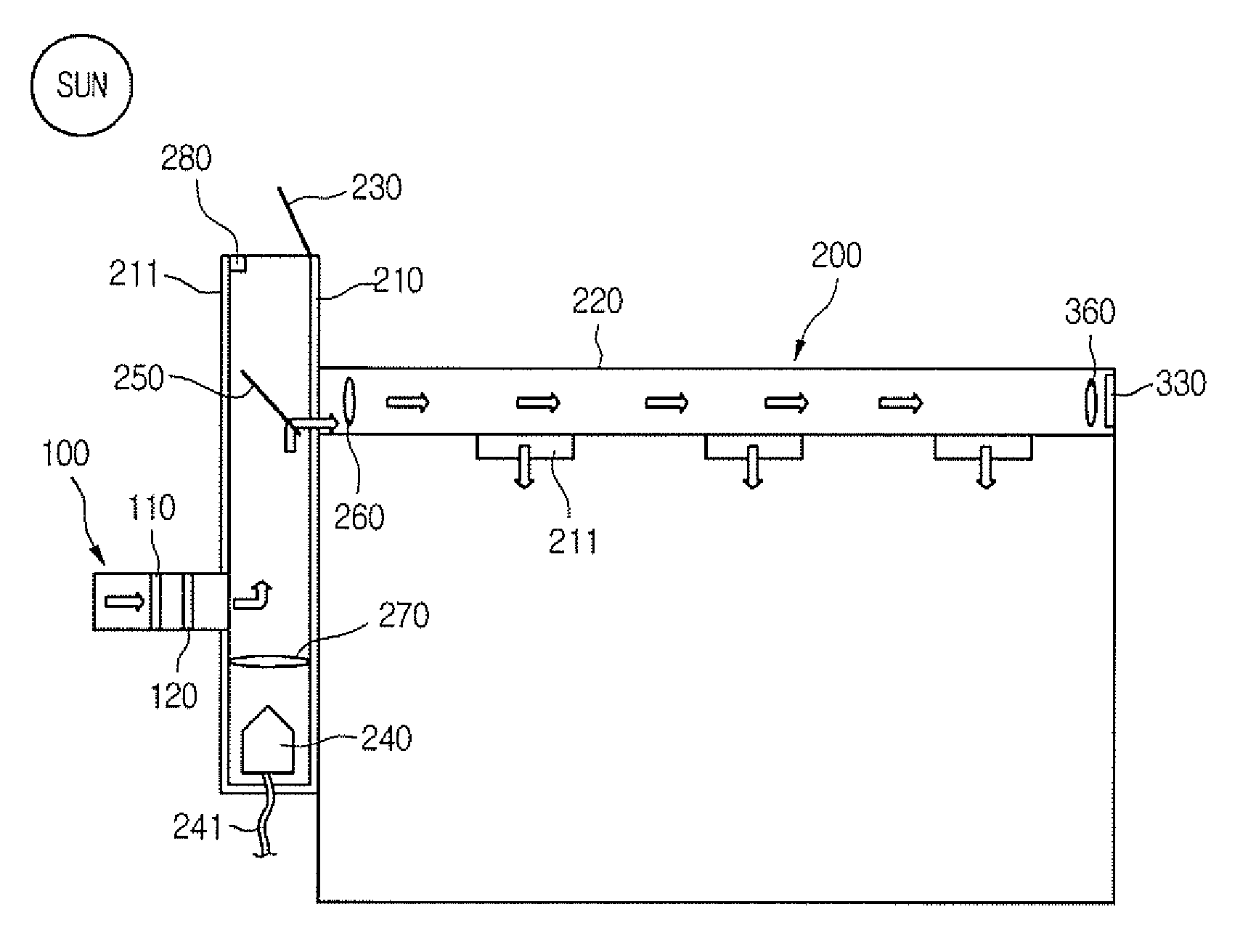
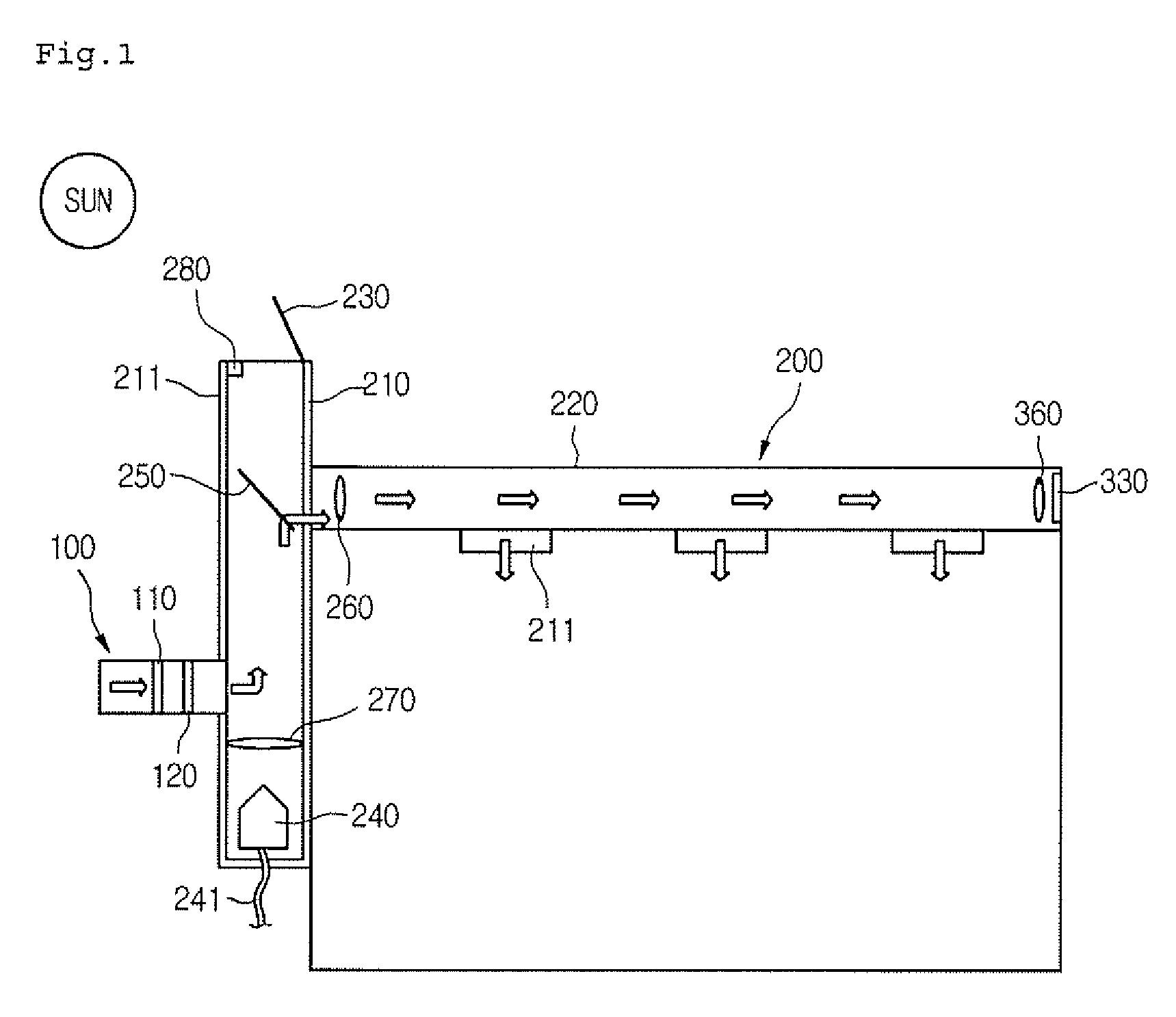
[0033]FIG. 1 is a schematic view of a ventilation system according to an embodiment of the present invention.

[0034] Referring to FIG. 1, a ventilation system 1 includes a ventilation device 100 for ventilating an indoor space, a ventilation duct 200 for guiding light and outdoor air, a light collection unit for directing natural light to the ventilation duct 200, and artificial light sources 240 and 330 for providing artificial light to the ventilation duct 200.

[0035] The ventilation duct 200 is connected t...


PUM


Abstract

Provided are a ventilation system and a method of controlling the ventilation system. The ventilation system includes a duct for directing indoor air and light to an indoor space, a solar cell converting natural light traveling along the duct into an electric energy, a light source converting the electric energy generated by the solar cell into artificial light and emitting the artificial light to the indoor space, and a ventilation device connected to the duct.

Description

BACKGROUND OF THE INVENTION [0001] 1. Field of the Invention [0002] The present invention relates to a ventilation system, and more particularly, to a ventilation system that has a solar cell disposed at a location that is not interfering with a path of sunlight and uses energy generated by the solar cell for the operation of an artificial lightening or the ventilation system [0003] 2. Description of the Related Art [0004] A conventional ventilation system includes a duct forming an airflow path and a fan assembly for introducing and exhausting indoor / outdoor air. [0005] In addition, a total heat exchanger that can partly recover a heat energy contained in the indoor air is installed in the ventilation system. [0006] Meanwhile, a conventional lightening system includes a lamp that artificially illuminates the indoor space. Recently, an optical pipe has been widely used to uniformly illuminate the indoor / outdoor spaces. The optical pipe totally reflects the light generated from the l...

Claims


Application Information

Patent Timeline
IPC IPC(8): F24F11/02
CPCF21S9/03F21V33/0088F24F5/0046F24F13/078F24F2005/0064F24F2221/02
Inventor CHOI, IN HOKIM, JEONG YONGCHOI, HO SEON
Owner LG ELECTRONICS INC
Why Eureka
Try Eureka