
Method of fabricating a conductive textile

a conductive textile and textile technology, applied in the field of functional textiles, can solve the problems of reducing the softness of textiles and reducing the electrical conductivity, and achieve the effect of increasing the conductivity of conductive textiles and reducing the resistance of conductive textiles

Inactive Publication Date: 2007-06-28
TAIWAN TEXTILE RESEARCH INSTITUTE
View PDF0 Cites 9 Cited by
  • Summary
  • Abstract
  • Description
  • Claims
  • Application Information

AI Technical Summary

Benefits of technology

The present invention provides a method of fabricating a conductive textile with increased conductivity and a uniform conductive film on the textile. The method involves roughening the surface of the textile to form erect-interlaced fibers, on which a conductive layer is formed to create an effective conductive path. This increases the surface area of the textile and reduces resistance, resulting in higher conductivity. The method can be carried out by scraping the surface of the textile or flocking short fibers on it. The conductive textile produced has better conductivity than prior art.

Problems solved by technology

However, since the conductive textile is only conductive through the metal fibers, it is conductive in only one dimension, not in a uniformly conductive plane.
However, unless the thickness of the conductive layer is increased, electrical conductivity is reduced because of bad step coverage of the conductive layer formed on the rough surface of the textile.
A thicker conductive layer formed on the textile, though, reduces the softness of the textile.

Method used


Image

  • Method of fabricating a conductive textile
  • Method of fabricating a conductive textile
  • Method of fabricating a conductive textile

Examples


embodiment 1

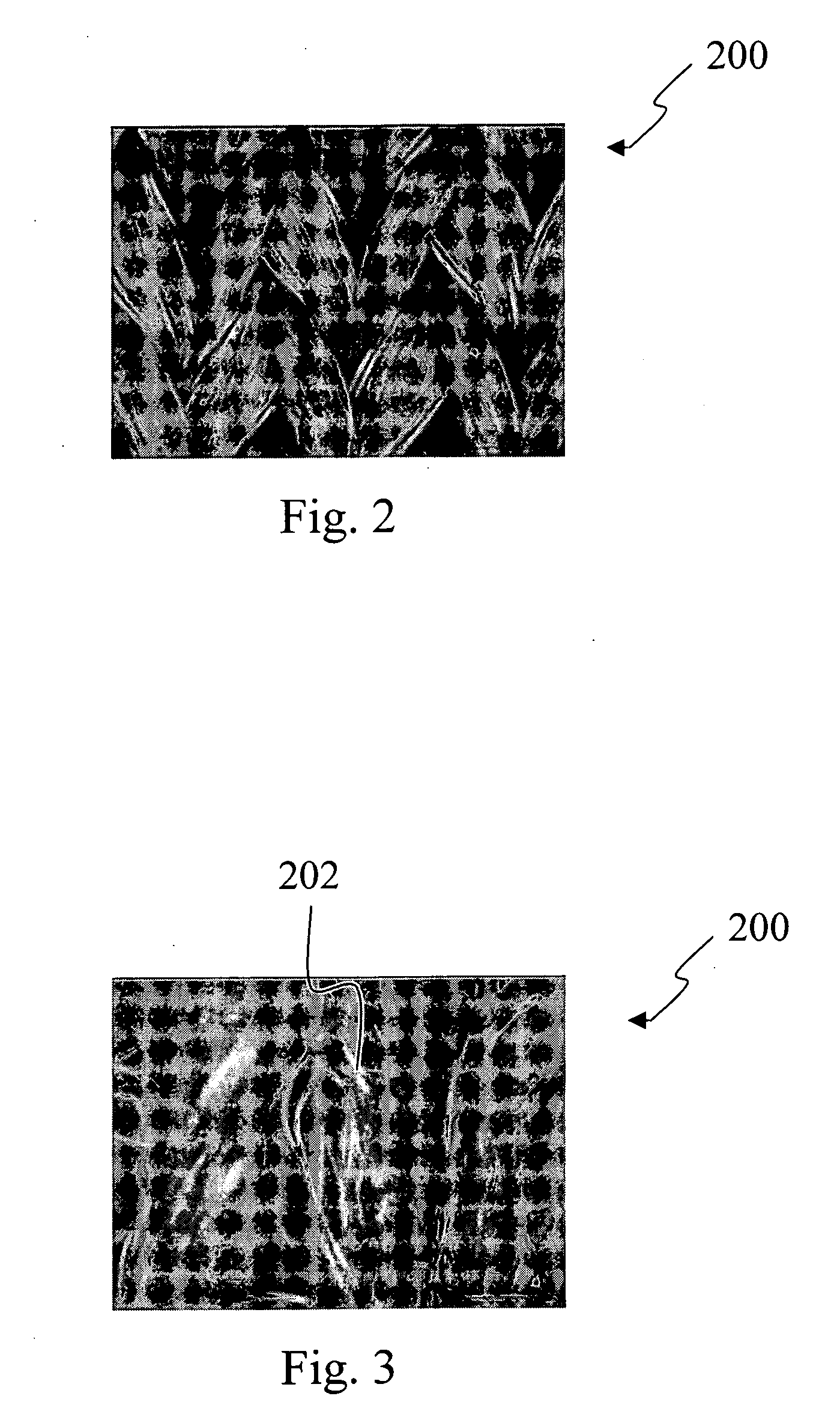
[0023] According to a preferred embodiment of the present invention, a scraping method is performed on the surface of the textile to form the erect-interlaced fibers. FIG. 2 is an electron microscope image showing a knitting fabric according to one embodiment of the present invention. First, according to a preferred embodiment of the present invention, a knitting fabric 200 is used as a textile. The surface of the knitting fabric 200 is scraped back and forth to form nap 202 (erect-interlaced fibers) on the surface of the knitting fabric 200, as shown in FIG. 3. The roughness degree of the surface of the knitting fabric 200 is according to demands. Alternatively, a fleece process can be performed after forming the nap 202 on the surface of the knitting fabric 200 according to demands to entwine the nap 202 on the surface of the knitting fabric 200 and increase the structural stability of the nap 202.

[0024] Then, a vacuum coating process is performed at a preferred pressure between ...

embodiment 2

[0027] According to another preferred embodiment of the present invention, a flocking method is performed on the surface of the textile to form the erect-interlaced fibers. FIG. 4 is an electron microscope image showing flocking fibers formed on the textile according to another embodiment of the present invention. First, adhesive is coated on a textile 200 to form an adhesive layer. Short fibers 204 are flocked on the adhesive layer of the surface of the textile 200 to form erect-interlaced fibers. The short fibers 204 are preferably less than 3 mm long and the diameter of the short fibers 204 is preferably less than 0.01 mm. The short fibers 204 are 1 mm long according to the embodiment of the present invention.

[0028] Next, a vacuum coating process is performed at a preferred pressure between 10−2 torr and 10−3 torr for about 20 minutes to sputter silver to form a silver layer on the surface of the erect-interlaced fibers and the textile. Consequently, a conductive textile is form...


PUM

PropertyMeasurementUnit
pressureaaaaaaaaaa
pressureaaaaaaaaaa
thicknessaaaaaaaaaa

Abstract

A method of fabricating a conductive textile is provided. First, erect-interlaced fibers are formed on a textile. Then, a conductive layer is formed on the erect-interlaced fibers and the surface of the textile to form a conductive textile.

Description

FIELD OF INVENTION [0001] The present invention relates to a method of fabricating a functional textile. More particularly, the present invention relates to a method of fabricating a conductive textile. DESCRIPTION OF RELATED ART [0002] With increases in living quality, the demand for functional textile, such as a conductive textile, fire-retardant textile, and antibacterial textile, has been raised. Conductive textile can be made into antistatic clothing, which is applied to industries requiring static protection, such as the petroleum industry, chemical industry, machinery industry, food products, and medicine. Furthermore, conductive textile can be applied in physical therapy, for example, in impulse electrotherapy used for stimulating reflex points of the palm and foot to reduce pain. [0003] There are two conventional methods of producing a conductive textile. One method is illustrated in FIG. 1, which is a schematic diagram showing a long metal fiber intertwined with a long non...

Claims


Application Information

Patent Timeline
Patent Type & Authority Applications(United States)
IPC IPC(8): B32B33/00B32B3/02
CPCB32B33/00B32B2038/0092B32B2305/18B32B2307/302C23C14/205D06M11/83D06M11/84Y10T428/23943Y10T428/2395Y10T428/23986
Inventor CHEN, SHIN-CHIEH
Owner TAIWAN TEXTILE RESEARCH INSTITUTE
Learn More