Image forming apparatus including shutter arm unit

Inactive Publication Date: 2007-06-28
HEWLETT PACKARD DEV CO LP
View PDF5 Cites 24 Cited by
  • Summary
  • Abstract
  • Description
  • Claims
  • Application Information

AI Technical Summary

Benefits of technology

[0013]An aspect of the present invention provides an image forming apparatus including a printing unit which prints an image on a sheet of paper, wherein a transportation path of the sheet of paper is arranged between the entrance and exit of the printing unit, and a shutter arm unit which includes a shutter arm and a stopper arm. The shutter arm is biased on standby at a first position, and in standby one end of the shutter arm protrudes toward the transportation path. When a first sheet of paper moving along the transportation path contacts the front end of the sheet of paper, the shutter arm swings to a second position. A stopper arm disposed on the shutter arm prevents additional sheets from moving along the transportation path at the same time as the first sheet of paper by protruding toward the transportation path when the shutter arm swings to the second position and blocking the front ends of the additional sheets.

Problems solved by technology

If two or more sheets of paper are moved through the printing unit simultaneously (a situation referred to as a multi-sheet feed), the extra sheets may cause a paper jam in the image forming apparatus, or may cause a printing defect in the images printed on the sheets of paper, such as by printing images intended to be printed on different sheets of paper onto the same sheet of paper.
Furthermore, the frictional force between the pick up roller and a top sheet of paper stacked on the knock up plate is greater than the transportation obstructing force of the finger members.
Although the various multi-sheet feed preventing units described above can prevent multiple sheets of paper from moving through the transportation path simultaneously, sometimes these various multi-sheet feed preventing units fail to prevent multi-sheet feeds.

Method used


Image

  • Image forming apparatus including shutter arm unit
  • Image forming apparatus including shutter arm unit
  • Image forming apparatus including shutter arm unit

Examples


Embodiment Construction

[0041]Reference will now be made in detail to the present embodiments of the present invention, examples of which are illustrated in the accompanying drawings, wherein like reference numerals refer to the like elements throughout. The embodiments are described below in order to explain the present invention by referring to the figures.

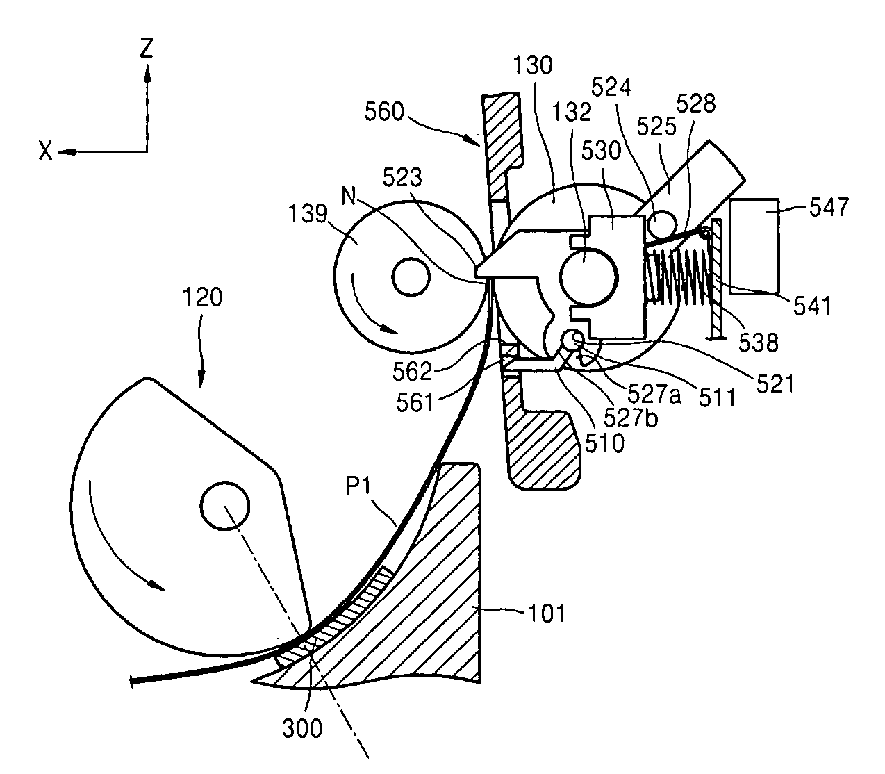
[0042]FIG. 1 is a side cross-sectional view which illustrates a main part of an image forming apparatus 100 according to an embodiment of the present invention. The image forming apparatus 100 includes a printing unit (not shown), a body 101, a sheet-feeding cassette 110, a door 102, a pick up roller 120, and a shutter arm unit 500. The printing unit and the door 102 are disposed in the body 101. The door 102 is connected to a side of the body 101 by a hinge, and opens and closes the body 101 to allow access to the printing unit and the transportation path of paper P. The printing unit which prints an image on paper P includes a light-scanning unit 180...


PUM


Abstract

An image forming apparatus includes a printing unit and a shutter arm unit. The shutter arm unit includes a shutter arm that swings to first and second positions, and a stopper arm, connected to the shutter arm, which protrudes toward a transportation path when the shutter arm swings to the second position in which the stopper arm prevents extra sheets of recording media from moving along the transportation path. The force of the paper moving along the transportation path swings the shutter arm unit into the second position, a protrusion cam and an escape cam prevent an increase in the return load of the shutter arm, and a pair of ends of the shutter arm aligns the front end of the sheet of paper.

Description

CROSS-REFERENCE TO RELATED APPLICATIONS[0001]This application claims the benefit of Korean Application No. 2005-129504, filed Dec. 26, 2005, in the Korean Intellectual Property Office, the disclosure of which is incorporated herein by reference.BACKGROUND OF THE INVENTION[0002]1. Field of the Invention[0003]Aspects of the present invention relate to an image forming apparatus, and more particularly, to an image forming apparatus which prevents a multi-sheet feed along a transportation path.[0004]2. Description of the Related Art[0005]Generally, an image forming apparatus, such as, for example, a printer, a copier, a fax machine, or a multifunctional apparatus includes a printing unit which prints an image onto a recording medium and a transportation path which transports the recording medium inside the printing unit. This recording medium may be various different types of media, such as a sheet of paper, a sheet of photographic printing paper, OHP film, etc., and will be referred to...

Claims


Application Information

Patent Timeline
IPC IPC(8): G03G15/00
CPCB41J11/006B41J11/0095B41J13/103B65H3/56B65H9/06B65H2404/722B65H2404/725B65H2801/06G03G15/6511G03G2215/00396G03G2221/1672G03G21/1638G03G15/00
Inventor LIM, KWANG-TAEK
Owner HEWLETT PACKARD DEV CO LP
Why Eureka
Try Eureka