
Integrated heat exchanger and heat exchanger

a heat exchanger and heat exchanger technology, applied in indirect heat exchangers, electric propulsion mountings, lighting and heating apparatuses, etc., can solve the problems of easy deformation of bearing surfaces, difficult to maintain the fixing condition between the condenser and the radiator, and the likelihood of deformation of bolts and nuts

Active Publication Date: 2007-06-28
DENSO CORP
View PDF16 Cites 45 Cited by
  • Summary
  • Abstract
  • Description
  • Claims
  • Application Information

AI Technical Summary

Benefits of technology

[0010] In this construction, since the first axis of the first bolt-receiving portion and the second axis of the second bolt-receiving portion are disposed nonparallel to each other, a shaft portion of the first bolt and a shaft portion of the second bolt are nonparallel to each other. Therefore, even if the integrated heat exchanger is subjected to vibrations in a direction parallel to the shaft portion of the first bolt, vibration loads are received not only by a bearing surface of the first bolt but also the shaft portion of the second bolt. As such, deformation and loosening of the bearing surface of the first bolt are reduced.
[0011] Likewise, even if the integrated heat exchanger is subjected to vibrations in a direction parallel to the shaft portion of the second bolt, deformation and loosening of a bearing surface of the second bolt is reduced. Accordingly, the plural heat exchangers are securely connected without causing deformation and loosening of the bolts even when affected by the vibrations.
[0013] In this construction, when the heat exchanger is mounted to an object with the first and second bolts, a shaft portion of the first bolt and a shaft portion of the second bolt are disposed nonparallel to each other. Therefore, even if the heat exchanger is subjected to vibrations in a direction parallel to the shaft portion of the first bolt, vibration loads are received not only by a bearing surface of the first bolt but also the shaft portion of the second bolt. Accordingly, deformation and loosening of the bearing surface of the first bolt are reduced.
[0014] Likewise, even if the heat exchanger is subjected to vibrations in a direction parallel to the shaft portion of the second bolt, deformation and loosening of a bearing surface of the second bolt are reduced. As such, the heat exchanger can be securely mounted to the object without causing deformation and loosening of the bolts even when affected by vibrations.
[0016] In this construction, shaft portions of the first and second bolts are disposed nonparallel to each other. Therefore, the heat exchanger can be securely connected to an object without causing deformation and loosening of the bolts.

Problems solved by technology

In this case, if the integrated heat exchanger is subjected to vibrations in the direction perpendicular to the heat exchanging parts, the bolts and nuts are likely to be deformed and become loose.
As a result, the bearing surfaces will be easily deformed, loosening the bolts.
Accordingly, it is difficult to maintain the fixing condition between the condenser and the radiator.

Method used


Image

  • Integrated heat exchanger and heat exchanger
  • Integrated heat exchanger and heat exchanger
  • Integrated heat exchanger and heat exchanger

Examples


Embodiment Construction

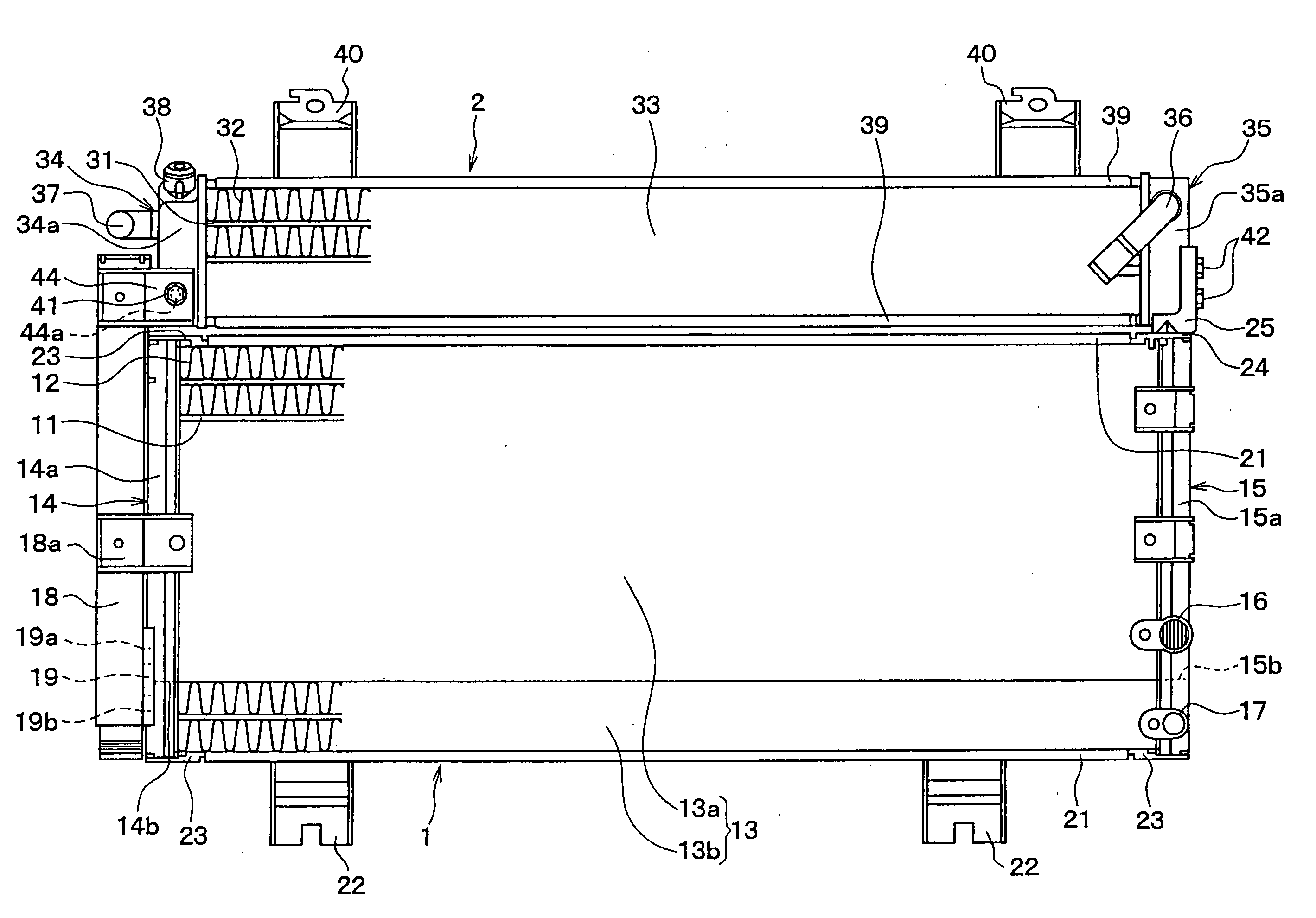
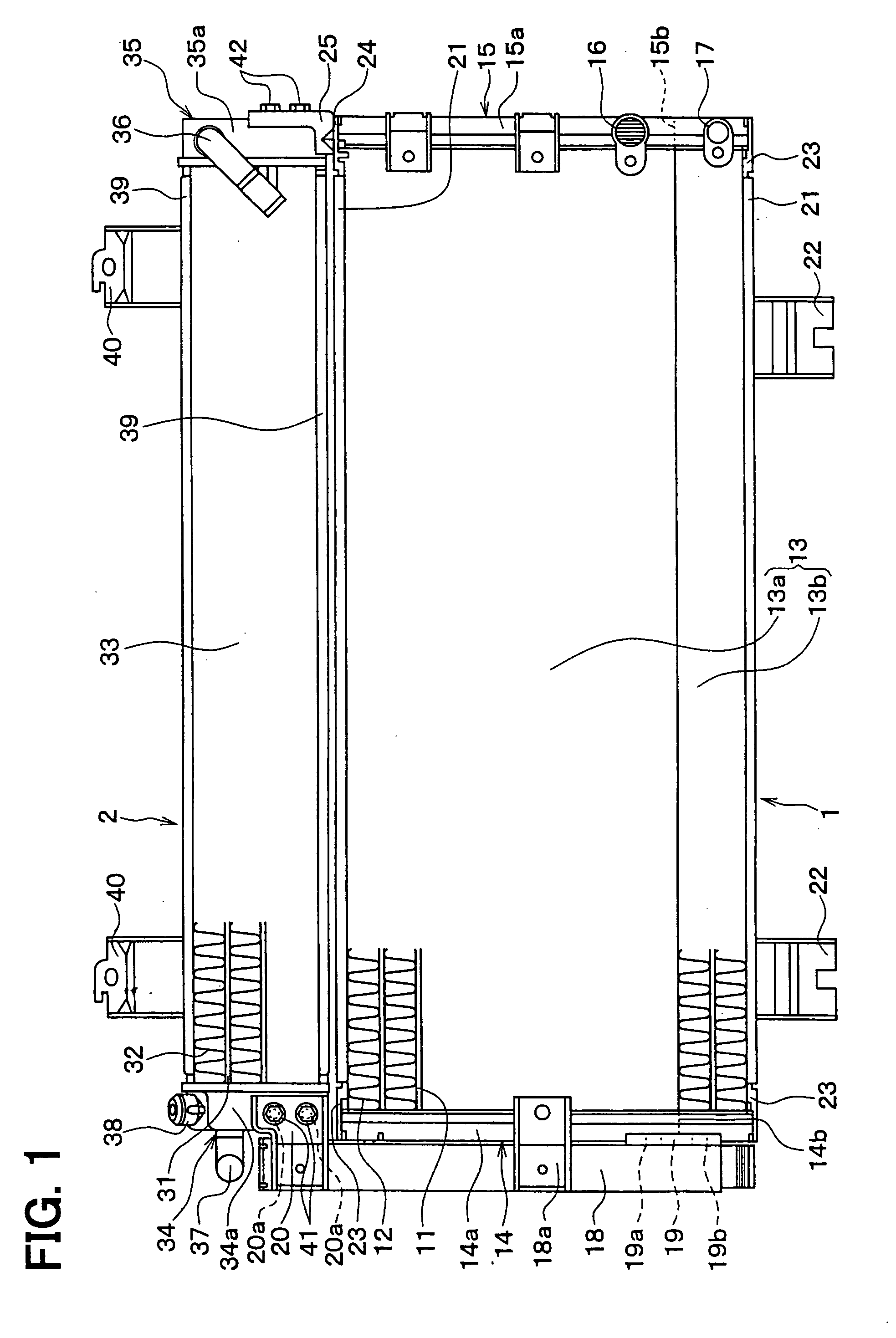
[0025] A first embodiment of the present invention will now be described with reference to FIGS. 1 to 4. As shown in FIG. 1, an integrated heat exchanger, which is for example used for a hybrid vehicle, has a condenser 1 as a first heat exchanger and an electric device cooling radiator 2 as a second heat exchanger. The condenser 1 and the electric device cooling radiator 2 are integrated with each other. The condenser 1 performs heat exchange between air and high temperature, high pressure refrigerant discharged from a compressor (not shown) of an air conditioner of the vehicle, thereby to condense the refrigerant. The electric device cooling radiator (hereafter, radiator) 2 is used for cooling electric devices (not shown) such as a generator, an inverter and an electric motor of the hybrid vehicle.

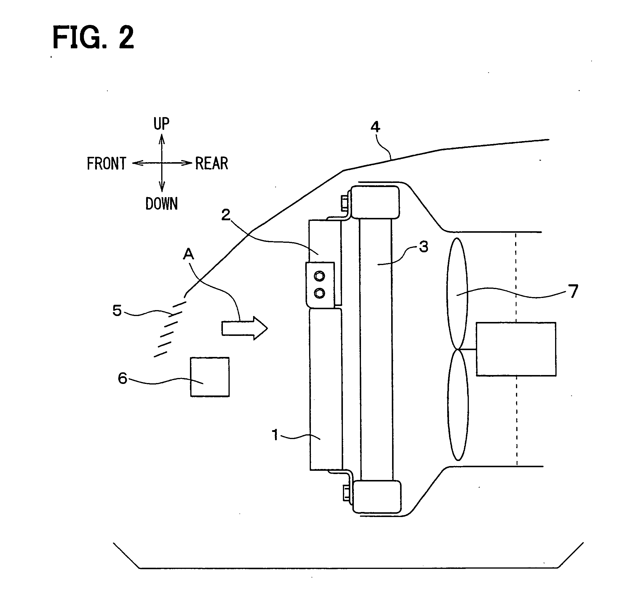
[0026] The integrated heat exchanger is mounted in an engine compartment of the vehicle, as shown in FIG. 2. In FIG. 2, an up and down arrow and a front and rear arrow denote directions ...


PUM


Abstract

An integrated heat exchanger has a first heat exchanger and a second heat exchanger. The first heat exchanger has a first bracket and a second bracket on header parts thereof, respectively. The first bracket and the second bracket are connected to header parts of the second heat exchanger with a first bolt and a second bolt, respectively, for integrating the first heat exchanger with the second heat exchanger. The header parts of the second heat exchanger are provided with a first bolt-receiving portion and a second bolt-receiving portions for receiving the first bolt and the second bolt therein, respectively. The first bolt-receiving portion and the second bolt-receiving portion define a first axis and a second axis, respectively. The first axis and the second axis are nonparallel to each other. Thus, the first bolt and the second bolt are disposed nonparallel to each other.

Description

CROSS REFERENCE TO RELATED APPLICATION [0001] This application is based on Japanese Patent Application No. 2005-372302 filed on Dec. 26, 2005, the disclosure of which is incorporated herein by reference. FIELD OF THE INVENTION [0002] The present invention relates to an integrated heat exchanger in which plural heat exchangers are integrated and a heat exchanger to be mounted to an object. BACKGROUND OF THE INVENTION [0003] An integrated heat exchanger in which plural heat exchangers are integrated is for example known in Japanese Patent Publication No. 2005-156067 (US 2005 / 0217832A1). In the integrated heat exchanger, a condenser for condensing refrigerant for a vehicle air conditioner and a radiator for cooling a cooling water of an electric motor for traveling are connected such that heat exchanging parts of the condenser and the radiator are disposed on the same plane and in parallel with respect to a flow direction of air. [0004] Further, each of the condenser and the radiator h...

Claims


Application Information

Patent Timeline
IPC IPC(8): F28F9/00B60K11/04
CPCB60K11/04F28D1/0452F28F9/002B60K2001/003B60K2001/006
Inventor SUGIMOTO, NAOKITSUZUKI, KAORU
Owner DENSO CORP
Learn More