
Automated chemical synthesizer and method for synthesis using same

a chemical synthesizer and automatic technology, applied in the direction of sequential/parallax process reactions, chemical apparatus and processes, chemical/physical/physico-chemical processes, etc., can solve the problems of requiring a substantial amount of time for reagent delivery, material splashing out, contamination between adjacent wells of the block,

Inactive Publication Date: 2007-06-21
CREOSLAUS
View PDF10 Cites 21 Cited by
  • Summary
  • Abstract
  • Description
  • Claims
  • Application Information

AI Technical Summary

Benefits of technology

"The present invention provides improved automated synthesizers that can deliver reagents to reaction wells faster and more accurately than traditional robotic arm systems. These synthesizers are reliable, economical, and eliminate cross-contamination by eliminating the need for the injection nozzle to travel over a reaction well. The reagents are dispensed directly from dedicated containers and nozzles, eliminating areas of contamination. The synthesizer also allows for individual processes to be paused, canceled, or restarted without affecting other processes. The control system allows for automatic generation of process steps and reagent volume calculations, as well as logging and analysis of communication and status messages. Additionally, the control system provides the ability to manually define steps and create reusable subroutines for efficient process creation."

Problems solved by technology

One deficiency is that the robotic arm moves slowly and must make a large number of moves, depending on the number of reactants in the finished product, between the source of reagent, wash solution and the reaction wells thus requiring a substantial amount of time for reagent delivery, particularly when carrying out a large number of reactions in a single block.
Those instruments that use a single probe or small number of probes on the robotic arm can result in contamination as the probes handle more than one reagent.
This agitation coupled with the conventional configuration of the reaction wells can result in splash out of material and contamination between adjacent wells of the block.
During this period the synthesizer cannot not be conveniently used for other synthesis until all reactions are complete.

Method used


Image

  • Automated chemical synthesizer and method for synthesis using same
  • Automated chemical synthesizer and method for synthesis using same
  • Automated chemical synthesizer and method for synthesis using same

Examples


Embodiment Construction

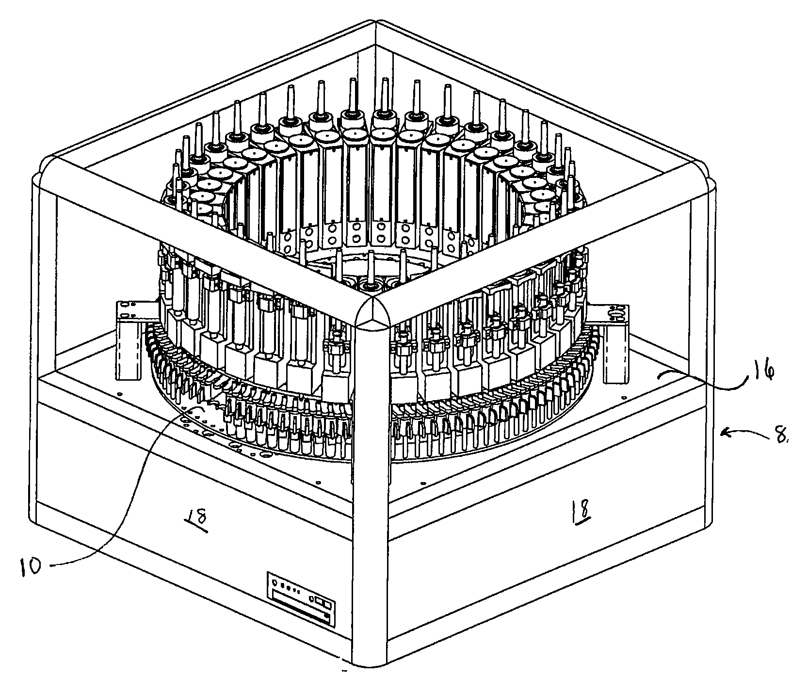
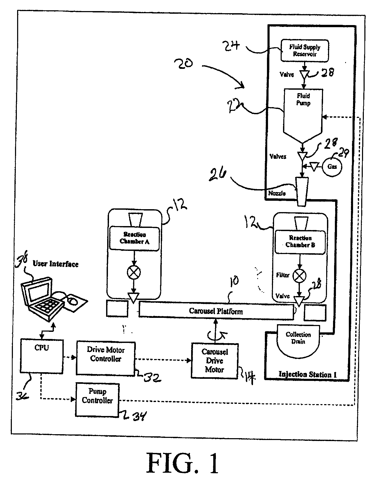
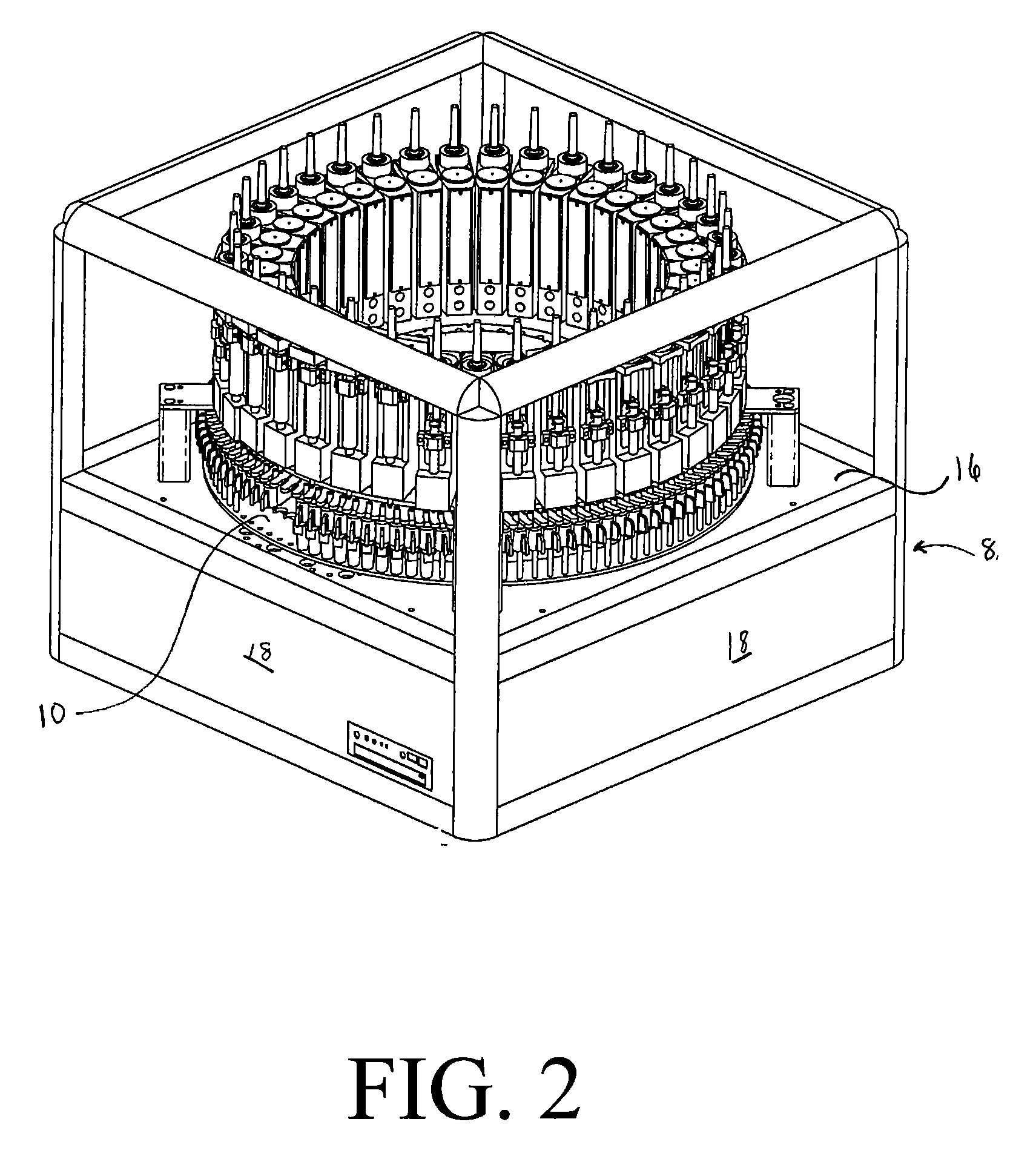
[0013] In accordance with one embodiment of the present invention, there is provided an improved automated synthesizer in which the reaction wells are moved into alignment with reactant and wash solution dispensing stations. The reactant and wash solution dispensing stations comprise stationary nozzles that are in communication with the source of reactants and / or wash solutions. By moving the wells rather than moving the nozzles for the delivery of reagents and wash solutions, the amount of time required to introduce reagent is substantially reduced. The number of washing steps required is reduced since a single dispensing nozzle delivers only one reagent so that a washing step is eliminated when a different reagent is to be delivered to a reaction well. The danger of cross-contamination due to the movement of a dispensing nozzle over the reaction block that can give rise to the possibility of small amounts of reagent from the nozzle gaining access into other reaction wells. Also co...


PUM


Abstract

An automated synthesizer is disclosed in which the reaction wells are moved by a carrier into alignment with stationary fluid delivery stations that are in communication with a source of reactants and / or wash solutions. In an alternate embodiment the delivery stations are moved into alignment with stationary reaction wells. A method for synthesizing chemical compounds employing the synthesizer is disclosed.

Description

[0001] This application is a continuation-in-part of application Ser. No. 11 / 372,818, filed Mar. 10, 2006, which application claims the benefit of the filing date of provisional application Ser. No. 60 / 735,276, entitled AUTOMATED ROTARY SYNTHESIZER both of which are incorporated by reference herein.FIELD OF THE INVENTION [0002] This invention relates to automated chemical synthesizers and more particularly to improved automated rotary chemical synthesizer. BACKGROUND OF THE INVENTION [0003] The production of chemicals and biochemicals and products such as, for example, peptides, proteins, carbohydrates and DNA and genetic material has been simplified with the advent of synthesizers which automatically or semi-automatically carry out the stepwise addition of reagents and carry out reactions, such as the synthesis of peptides, or for carrying out fragment coupling reactions. Conventionally, fully automated synthesizers include a robotic arm that carries a vertically moveable probe for...

Claims


Application Information

Patent Timeline
Patent Type & Authority Applications(United States)
IPC IPC(8): B01J19/00
CPCB01J19/0046B01J2219/00283B01J2219/00326B01J2219/0036B01J2219/00423B01J2219/00545B01J2219/00547B01J2219/00585B01J2219/0059B01J2219/00596B01J2219/00599B01J2219/00689B01J2219/00704B01J2219/00725C40B60/14
Inventor PHELPS, DAVID Y.
Owner CREOSLAUS
Learn More