
Revolutionary solar collecting system

a solar collector and solar energy technology, applied in the field of solar collectors, can solve the problems of cumbersome systems, difficult and unavailability at all hours, and high manufacturing and maintenance costs, and achieve the effects of efficient conversion of sun energy into electricity, heat energy and/or steam, and easy adjustmen

Inactive Publication Date: 2007-06-21
TARABISHI M HISHAM
View PDF11 Cites 25 Cited by
  • Summary
  • Abstract
  • Description
  • Claims
  • Application Information

AI Technical Summary

Benefits of technology

[0009] It is a further object of the invention to provide a solar energy collecting system that is capable of efficiently converting energy from the sun into electricity, heat energy and / or steam.
[0010] It is yet another object of the invention to provide a solar energy collecting system that is capable of being easily adjusted to maximize the sun's rays across the arc of the sky and according to seasonal changes.
[0011] It is still yet another object of the invention to provide a solar energy collecting system that is capable of condensing the sun's rays and redirecting them as needed to maximize their energy potential.

Problems solved by technology

Although solar energy is abundant, a major drawback is that it is diffuse and not available at all hours.
Unfortunately, these systems are cumbersome, expensive to manufacture and maintain, expensive to operate and yield little in terms of usable, convertible energy.
Although state and federal incentives are available, it is not yet economical to harness solar energy on a large scale to produce electricity.
However, the high cost of traditional energy sources and the energy shortage are presenting a significant burden on many countries.
Also, these traditional sources have numerous drawbacks such as pollution and the limited amounts of fossil fuels available.

Method used


Image

  • Revolutionary solar collecting system
  • Revolutionary solar collecting system
  • Revolutionary solar collecting system

Examples


Embodiment Construction

, it should be noted that identical components having identical functions have been designated with identical reference numerals for the sake of clarity.

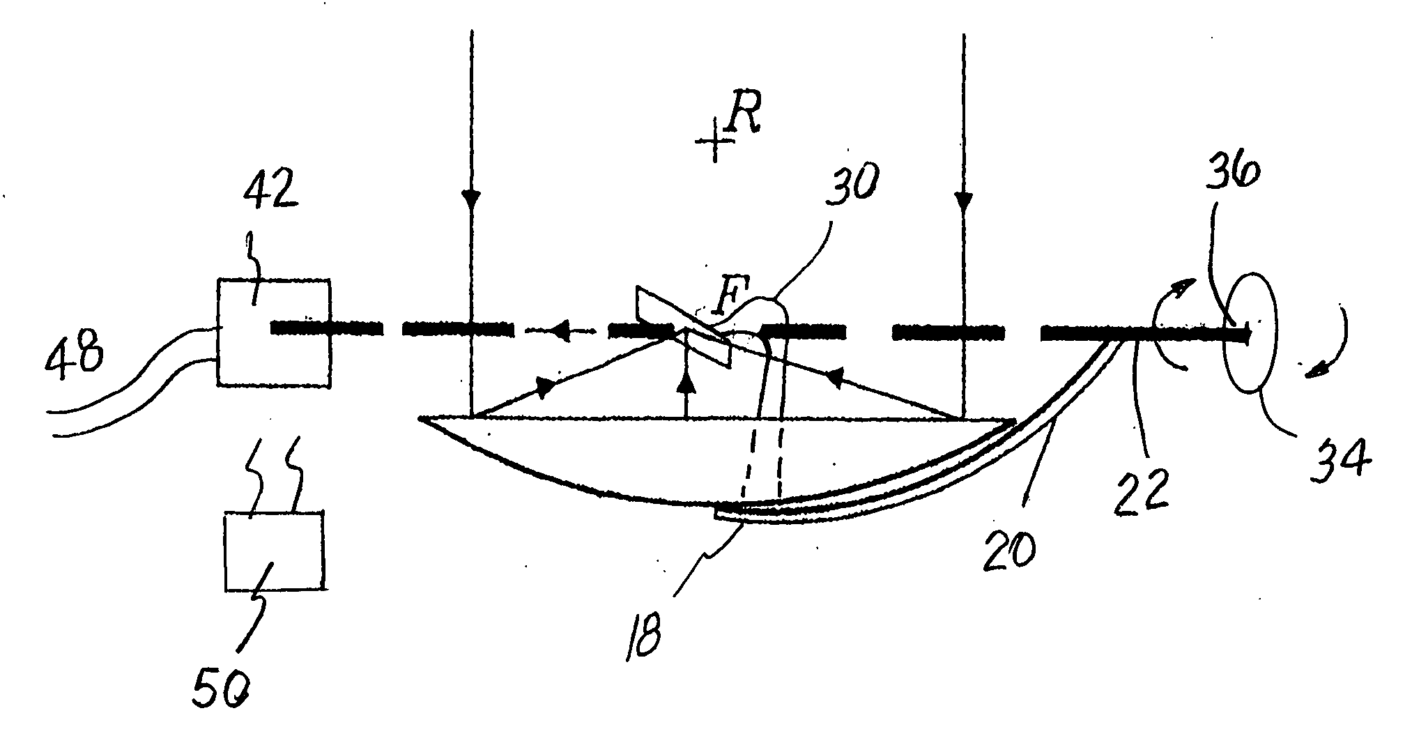
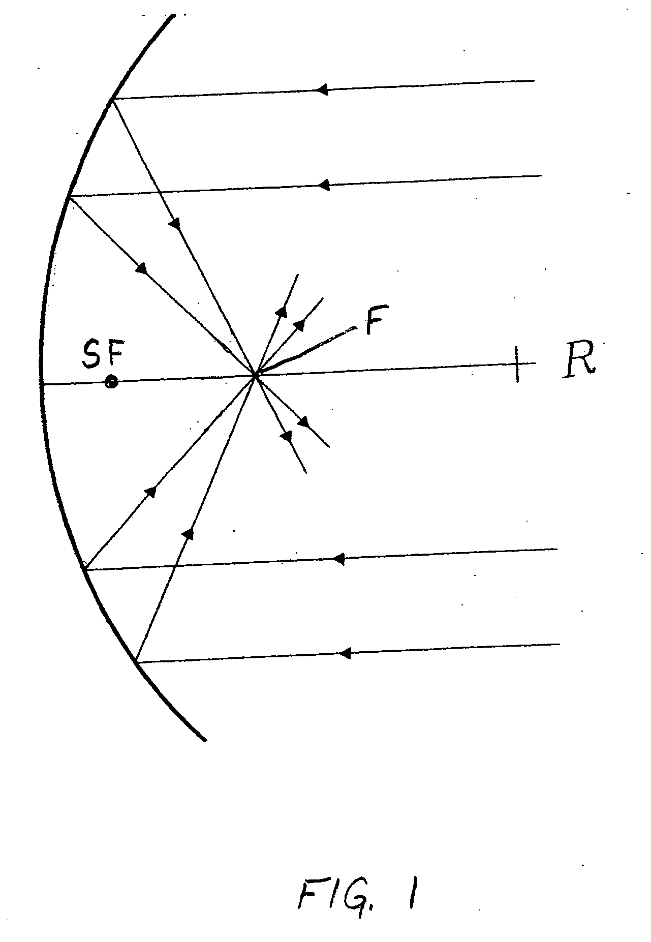
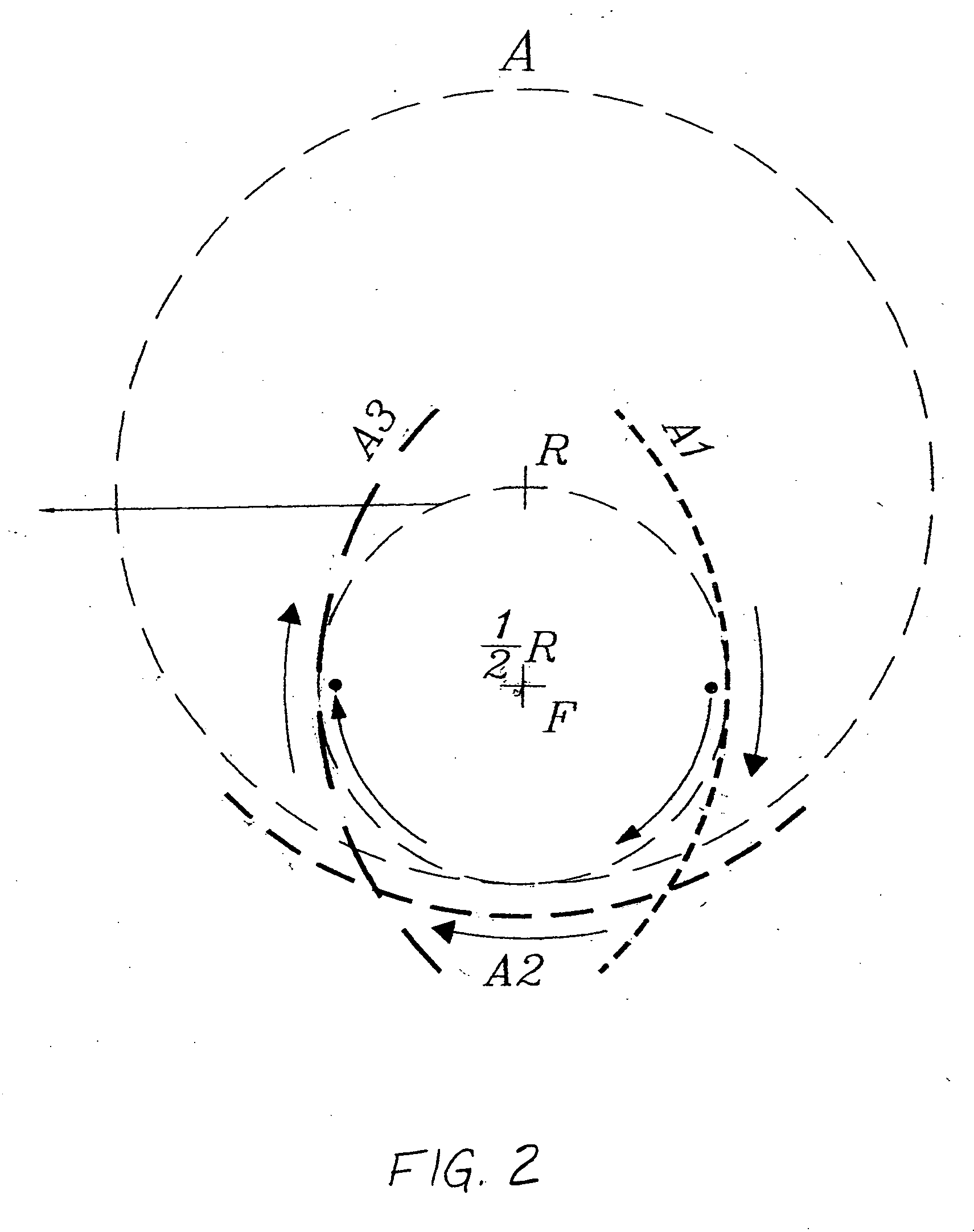
[0031] In order to adequately harness the sun's energy, it is necessary for a solar collector system to use a solar collector panel that is formed from a reflective material and has a substantial surface area. The best types of these collectors are in the form of a parabolic or concave mirror(s) having a predetermined radius. The rays from the sun shine down upon the surface of the collector panel and reflect back to what is called a “focal point”. This focal point is ½ the radius of the parabolic collector panel. These rays become condensed at the focal point. By controlling the path of these condensed rays and then redirecting these rays as a single beam to a collecting and / or converting device, one is able to generate and convert a large amount of energy into a usable resource.

[0032] Referring now to FIGS. 3-12, there is shown a...


PUM


Abstract

A revolutionary solar collecting system for effectively and efficiently harnessing the sun's energy is shown. This system tracks the sun and maintains a constant focal point or sub-focal point to at least partially condense the sun's rays into a high-energy beam that is then redirected to a predetermined location for generating electrical power, heat energy, steam, and / or any other well-known application. The revolutionary system of the invention is low-cost, low maintenance, and is capable of significantly reducing energy costs.

Description

CROSS-REFERENCES TO RELATED APPLICATIONS [0001] This application is based on Provisional Application Ser. No. 60 / 751,694, filed Dec. 19, 2005 and Provisional Application Ser. No. 60 / 834,208, filed Jul. 28, 2006.FIELD OF THE INVENTION [0002] The present invention relates, in general, to a solar collecting system and, more particularly, to a solar collecting system that tracks the sun and maintains a constant focal point or sub-focal point to at least partially condense the sun's rays into a high-energy beam that is then redirected to a predetermined location for generating electrical power, heat energy, steam, and / or any other well-known application. BACKGROUND OF THE INVENTION [0003] Solar energy has been available as a source of power for more than 4.5 billion years. For centuries, inventors have been devising various means to harness this energy. As far back as the third century B.C., records indicate that the Greek and Roman armies used “burning mirrors” to focus sunlight as weap...

Claims


Application Information

Patent Timeline
Patent Type & Authority Applications(United States)
IPC IPC(8): F24J2/38F24S50/20
CPCF24J2/08F24J2/12F24J2/18F24J2/38F24J2/4625H01L31/0547Y02E10/47Y02E10/52Y02E10/60H02S40/44Y02E10/42F24S23/71F24S50/20F24S23/79F24S40/55F24S23/30Y02P80/20Y02E10/40
Inventor TARABISHI, M. HISHAM
Owner TARABISHI M HISHAM
Learn More