
Safety railing for building construction

Inactive Publication Date: 2007-06-21
SHYMKOWICH DENNIS J
View PDF3 Cites 39 Cited by
  • Summary
  • Abstract
  • Description
  • Claims
  • Application Information

AI Technical Summary

Benefits of technology

[0009] With the method according to the present invention, there is no need to drill into the concrete floor or the walls or columns of the building and, therefore, no risk of damage caused by such drilling. Also, there is a substantial saving of work as compared with the above-described conventional method of installing safety railings.
[0011] The socket supports extend to the underside of the newly cast concrete floor, which in accordance with conventional building construction practice is then ground prior to the application of a finish layer to the underside of the concrete floor. The grinding operation serves to smoothen any projection by the lower ends of the socket supports at the underside of the concrete floor.
[0013] During the casting of the concrete to form the concrete floor, the post sockets can be covered by lids, which prevent concrete from entering into the post sockets and which, thereby, facilitate the insertion of the posts into the post sockets. These lids are then removed before the insertion of the posts into the post sockets. When the safety railing is no longer required on the concrete floor, the rails and the posts can be removed. The post sockets are then filled and concealed by the application of a finish layout onto the top of the concrete floor.

Problems solved by technology

It is, however, a disadvantage of this prior method that it is very labor intensive, since in practice it is usually necessary to have such railing installation performed by at least one construction worker, who is dedicated to that task and who is normally kept so busy by this work that he is unavailable for other work on the building site.
Also, the drilling into the concrete involves the risk of breakage and consequential repairs and may cause damage to wiring or pipes embedded in the concrete.

Method used


Image

  • Safety railing for building construction
  • Safety railing for building construction
  • Safety railing for building construction

Examples


Embodiment Construction

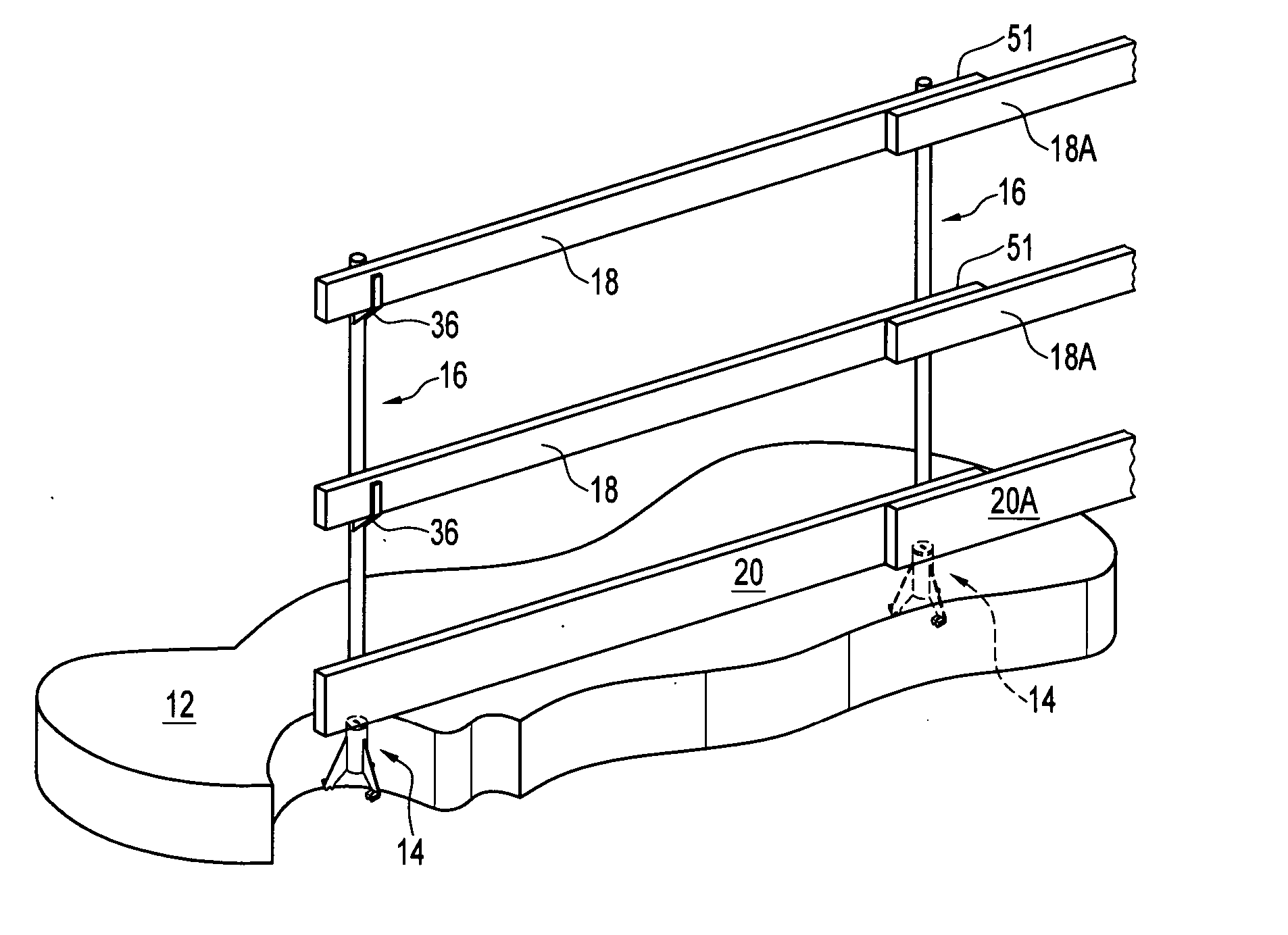
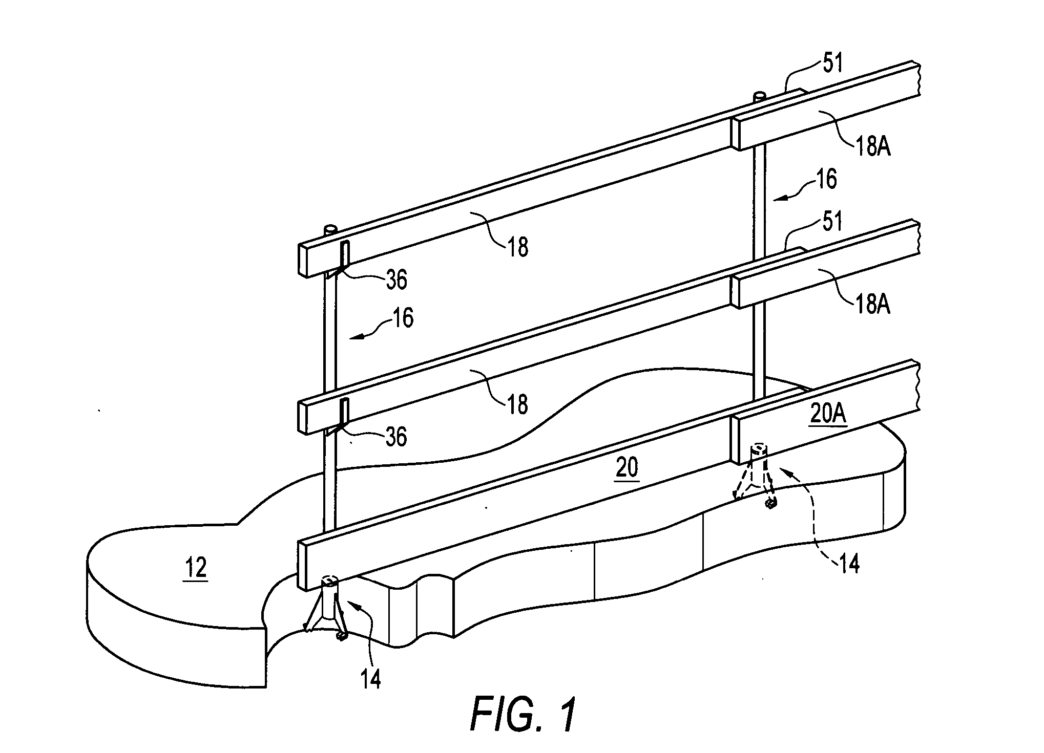
[0031] In FIG. 1 of the accompanying drawings, there is shown a safety railing, indicated generally by reference 10, which is installed on a concrete floor 12. The safety railing 10 has post sockets, of which only one is shown in FIG. 1 and is indicated generally by reference numeral 14, posts indicated generally by reference numerals 16, and horizontal rails 18 supported on the posts 16. A lowermost rail, commonly referred to in the construction industry as a “kick rail”, is indicated by reference numeral 20 and supported on the concrete floor 12 by the posts 16.

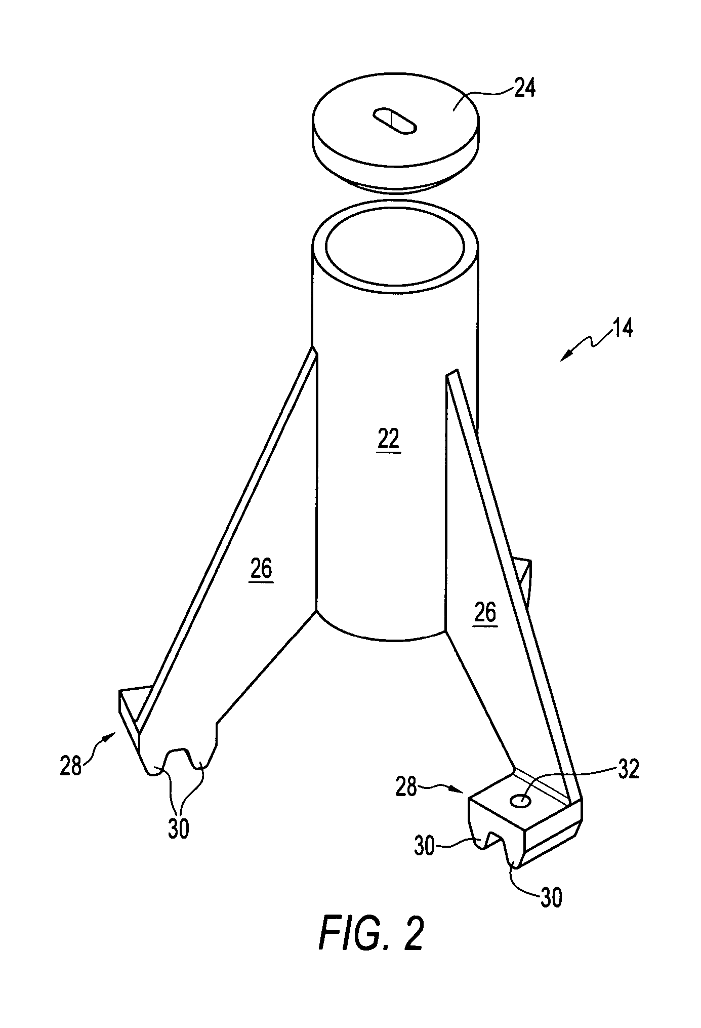
[0032] One of the post supports 14 is illustrated in greater detail in FIGS. 2 through 4, and comprises an open-topped cylindrical post socket 22, with a circular lid 24 for closing the top of the cylindrical post socket 22.

[0033] The cylindrical post socket 22 is provided on a socket supports formed by three legs or support members in the form of flanges 26, which are equi-angularly spaced apart around the cylindrical po...


PUM


Abstract

A method of installing a safety railing in a building under construction by providing post supports comprising open-topped post sockets on socket supports, mounting the post sockets on a concrete floor formwork with the post sockets spaced above the concrete floor formwork by the socket supports and casting concrete to form a concrete floor on the concrete floor formwork and thereby embedding the post supports in the concrete floor with the concrete extending beneath the post sockets. The lower ends of posts are then inserted into the post sockets to support the posts above the concrete floor and rails are supported on the posts.

Description

BACKGROUND OF THE INVENTION [0001] 1. Field of the Invention [0002] The present invention relates to methods of installing safety railings in buildings under construction, to safety railings and to post support for use in safety railings. [0003] 2. Description of the Related Art [0004] In the construction of a multi-floor concrete building, concrete floor formworks are employed for the casting of the floors in succession. As each floor is cast, it is necessary to install a temporary safety railing around the periphery of that floor, so that workers are prevented from falling from that floor. When the work on that floor by the workers has been completed, the safety railing is removed. [0005] At present, the conventional method of installing such a safety railing is to secure brackets by nailing the brackets to the columns of the building under construction. These brackets are then employed to support horizontal rails. Also, it is common to gather scrap lumber on a building site and t...

Claims


Application Information

Patent Timeline
IPC IPC(8): E04B1/38
CPCE04B1/4114E04G5/04E04G15/061E04G21/3223E04G5/046
Inventor SHYMKOWICH, DENNIS J.
Owner SHYMKOWICH DENNIS J
Learn More