
Method of vertical handoff

a vertical handoff and handoff technology, applied in the field of vertical handoff, can solve the problems signal strength cannot be used as triggering information for handoff decision, and cannot solve the problem of low data rate with high cos

Inactive Publication Date: 2007-06-14
KT CORP +2
View PDF5 Cites 48 Cited by
  • Summary
  • Abstract
  • Description
  • Claims
  • Application Information

AI Technical Summary

Benefits of technology

[0041] An exemplary vertical handoff method according to another embodiment of the present invention is provided to a mobile station that can access a first network having a relatively wide service coverage and a second network having a relatively narrow service coverage in an area where service coverages of heterogeneous networks are overlapped, wherein the first network is a serving network of the mobile station. The vertical handoff method includes: (a) checking whether a received signal strength () that is greater than a first threshold value among received signal strengths received from the second network exists; (b) when a received signal strength that is greater than the first threshold value exists, predicting a transition pattern based on the received signal strengths that have been received for a predetermined time period; (c) when the received signal strength increases according to a result of the transition pattern prediction, deciding first vertical handoff to a target network, which is the second network; and (d) when the received signal strength decreases according to a result of the transition pattern prediction, remaining in the serving network

Problems solved by technology

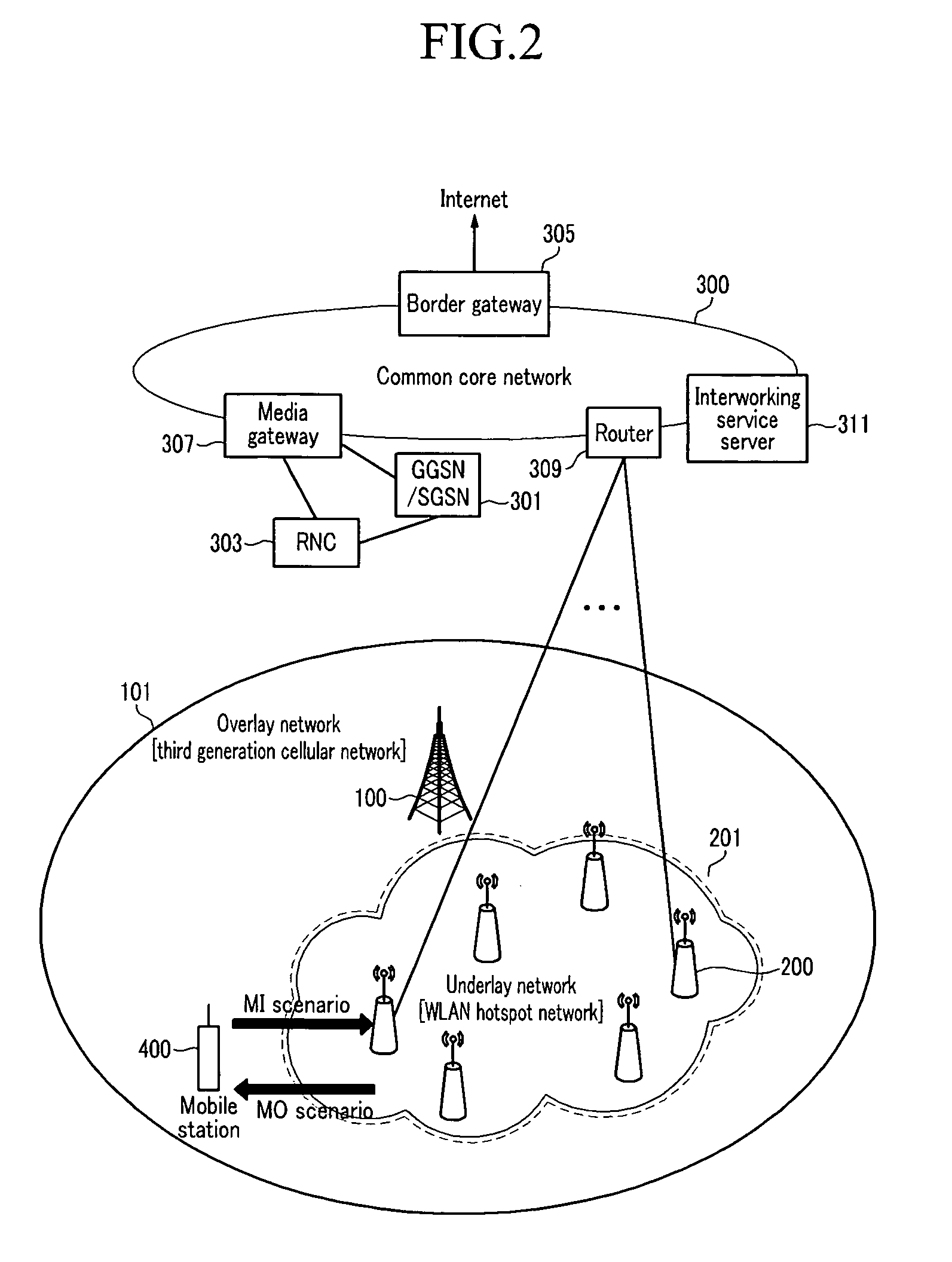
In general, the third generation cellular network provides global coverage but it has a low data rate with high cost.
However, the vertical handoff cannot be decided by comparing signal strengths because there are no signal strengths that can be compared.
Since the third generation cellular network has global service coverage, signal strength cannot be used as triggering information for handoff decision.
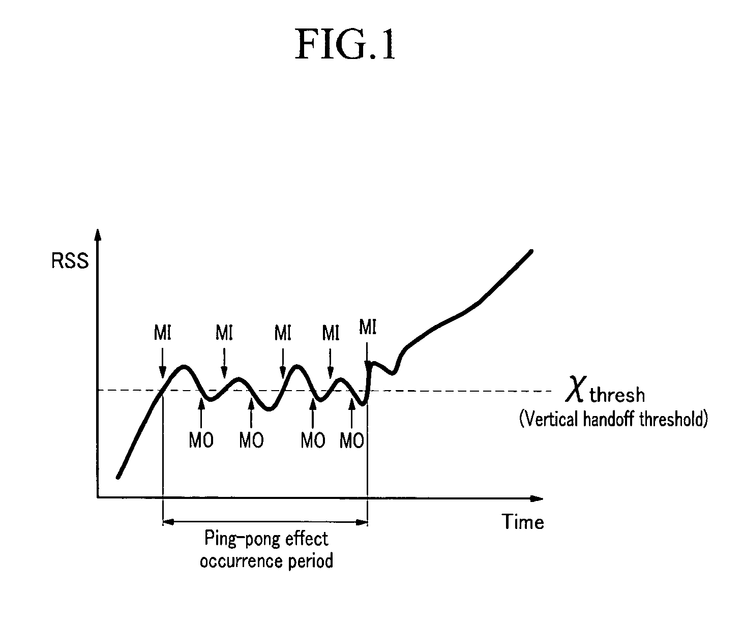
However, since the vertical handoff has no triggering information that can be compared except for a signal strength of the WLAN hotspot network that provides the limited service coverage, the vertical handoff has the higher probability of occurrence of the ping-pong effect.
In addition, the mobile station in the middle of performing a vertical handoff to the WLAN hotspot network may be forced to perform a vertical handoff to the third generation cellular network due to the limited coverage of the WLAN hotspot network.
Such a phenomenon may increase a failure probability of the vertical handoff.
However, the ping-pong effect in the vertical handoff may give a heavier load to a system compared to the horizontal handoff due to characteristics of the vertical handoff, and therefore it is highly required to minimize the ping-pong effect.
However, although the target wireless network guarantees the constant performance of the mobile station during the stability period Ts, irregular mobility of the mobile station may cause inconsistent performance.
Accordingly, this prior art cannot efficiently prevent the ping-pong effect.
However, the received signal strength of the mobile station cannot be linear due to irregular characteristics of the wireless network environment.
Due to such a ping-pong effect, the mobile station cannot find an appropriate time to perform the vertical handoff, and therefore the failure probability of the vertical handoff is increased, causing performance deterioration.
Moreover, conventionally, reduction of one received signal strength among received signal strengths received during a predetermined time period causes the mobile station to not perform a vertical handoff.
Thus, when handoff decision is made by one received signal strength, the vertical handoff decision may not be made even though a strong enough received signal strength is received from the WLAN hotspot network.

Method used


Image

  • Method of vertical handoff
  • Method of vertical handoff
  • Method of vertical handoff

Examples


Embodiment Construction

[0050] An exemplary embodiment of the present invention will hereinafter be described in detail with reference to the accompanying drawings.

[0051] In the following detailed description, only certain exemplary embodiments of the present invention have been shown and described, simply by way of illustration. As those skilled in the art would realize, the described embodiments may be modified in various different ways, all without departing from the spirit or scope of the present invention. Accordingly, the drawings and description are to be regarded as illustrative in nature and not restrictive. Like reference numerals designate like elements throughout the specification. In addition, throughout this specification and the claims which follow, unless explicitly described to the contrary, the word “comprise / include” or variations such as “comprises / includes” or “comprising / including” will be understood to imply the inclusion of stated elements but not the exclusion of any other element...


PUM


Abstract

The present invention relates to a vertical handoff method. According to the present invention, a serving network of a mobile station is determined. Herein, the mobile station that can access a first network having relatively wide service coverage and a second network having relatively narrow service coverage in an area where service coverages of heterogeneous networks are overlapped. When accessing the serving network of the first network, it is determined whether a received signal strength received from the second network is greater than a first threshold value. In addition, a first vertical handoff is decided by using a result of prediction of a transition pattern of the received signal strength that is greater than the first threshold value. When the serving network is the second network, it is determined whether the received signal strength received from the second network is less than a second threshold value. By using a result of prediction of a transition pattern of the received signal strength that is less than the second threshold value, a second vertical handoff is decided. Herein, the first threshold value is greater than the second threshold value.

Description

CROSS-REFERENCE TO RELATED APPLICATION [0001] This application claims priority to and the benefit of Korean Patent Application Nos. 10-2005-0121363 and 10-2006-0040604 filed in the Korean Intellectual Property Office on Dec. 10, 2005, and on May 4, 2006 the entire contents of which are incorporated herein by reference. BACKGROUND OF THE INVENTION [0002] (a) Field of the Invention [0003] The present invention relates to a vertical handoff method, and more particularly, the present invention relates to a vertical handoff method of a mobile station that can access a first network having relatively wide service coverage and a second network having relatively narrow service coverage in an area where service coverages of heterogeneous networks are overlapped. [0004] (b) Description of the Related Art [0005] It is expected that a next generation network will evolve into an Internet protocol (IP)-based wireless network with overlapped service areas. That is, heterogeneous wireless networks ...

Claims


Application Information

Patent Timeline
IPC IPC(8): H04Q7/00H04W36/14H04W88/06
CPCH04W36/04H04W36/30H04W88/06H04W36/304Y02D30/70
Inventor KIM, WON-IKLEE, BONG-JUBAEK, SEUNG-KWONKIM, SOO-CHANGSHIN, YEON-SEUNGKIM, YEONG-JIN
Owner KT CORP
Learn More