
Method and apparatus for applying railway ballast

a technology of ballast and railways, applied in the direction of process and machine control, instruments, ways, etc., can solve the problems of delay in deliveries and loss of incom

Inactive Publication Date: 2007-06-07
HERZOG CONTRACTING
View PDF34 Cites 30 Cited by
  • Summary
  • Abstract
  • Description
  • Claims
  • Application Information

AI Technical Summary

Benefits of technology

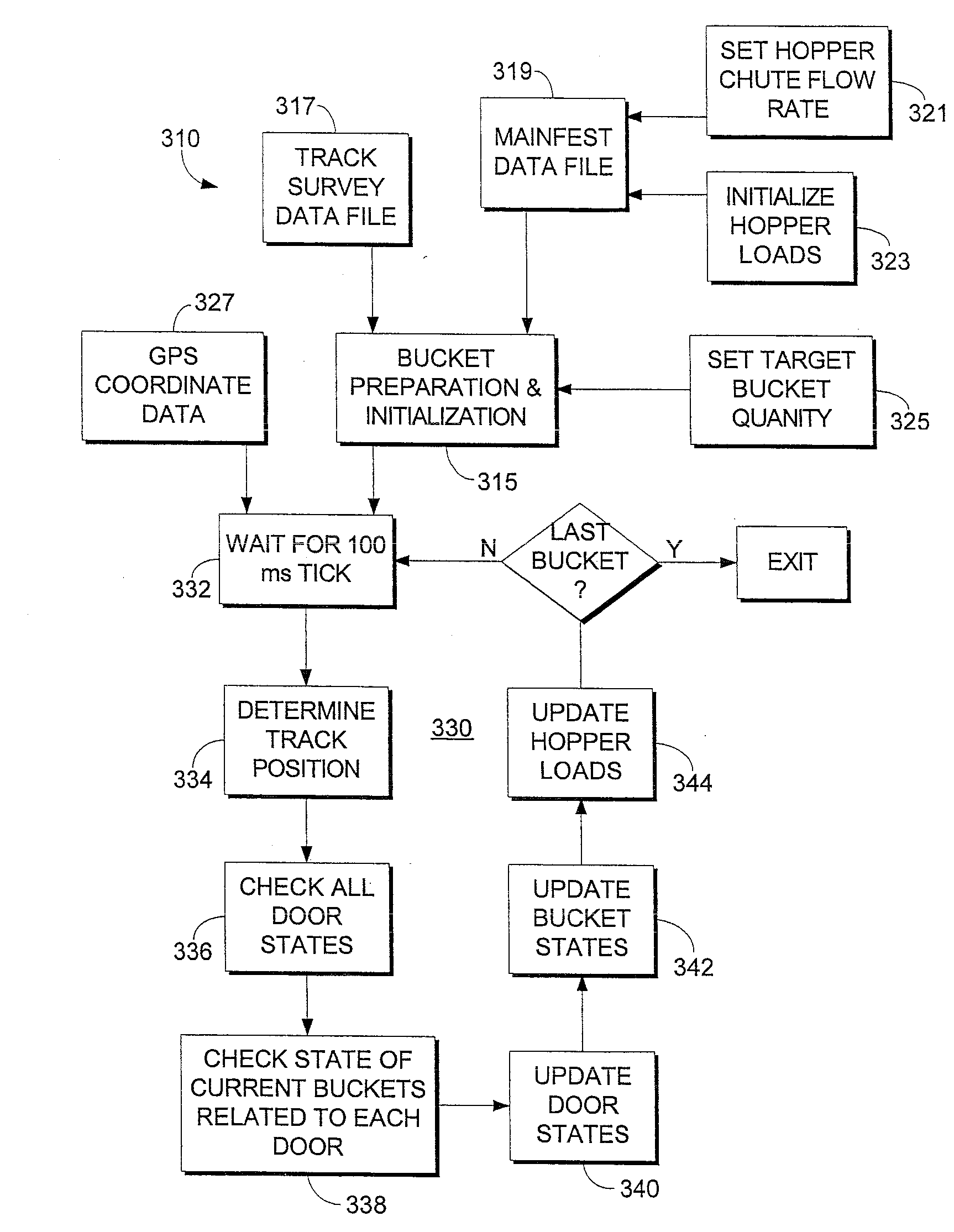
[0008] The present invention provides methods and apparatus for controlled spreading of ballast on a railroad on a large scale basis using multiple ballast hopper cars spreading simultaneously, at times. The system of the present invention uses various different techniques for determining where ballast needs to be applied and for controlling the opening of ballast doors to spread controlled quantities of ballast on sections where ballast is desired and to inhibit spreading ballast where not desired or not needed. The system allows the ballast train to spread ballast mostly at a high enough speed that normal traffic on the railroad on which it is operating is only minimally affected by its presence.
[0020] The present invention contemplates a variety of methods and apparatus for determining the location where ballast is to be spread along a railway bed and applying using a gyroscope for stabilization and one or more accelerometers for determining forward and angular momentums. This inertial system can be augmented using various position reference techniques to improve the overall accuracy and reliability.

Problems solved by technology

Both conventional control methods are slow and thus disruptive to normal traffic on the railroad section being maintained, thereby causing delays in deliveries and loss of income.

Method used


Image

  • Method and apparatus for applying railway ballast
  • Method and apparatus for applying railway ballast
  • Method and apparatus for applying railway ballast

Examples


Embodiment Construction

[0061] As required, detailed embodiments of the present invention are disclosed herein; however, it is to be understood that the disclosed embodiments are merely exemplary of the invention, which may be embodied in various forms. Therefore, specific structural and functional details disclosed herein are not to be interpreted as limiting, but merely as a basis for the claims and as a representative basis for teaching one skilled in the art to variously employ the present invention in virtually any appropriately detailed structure.

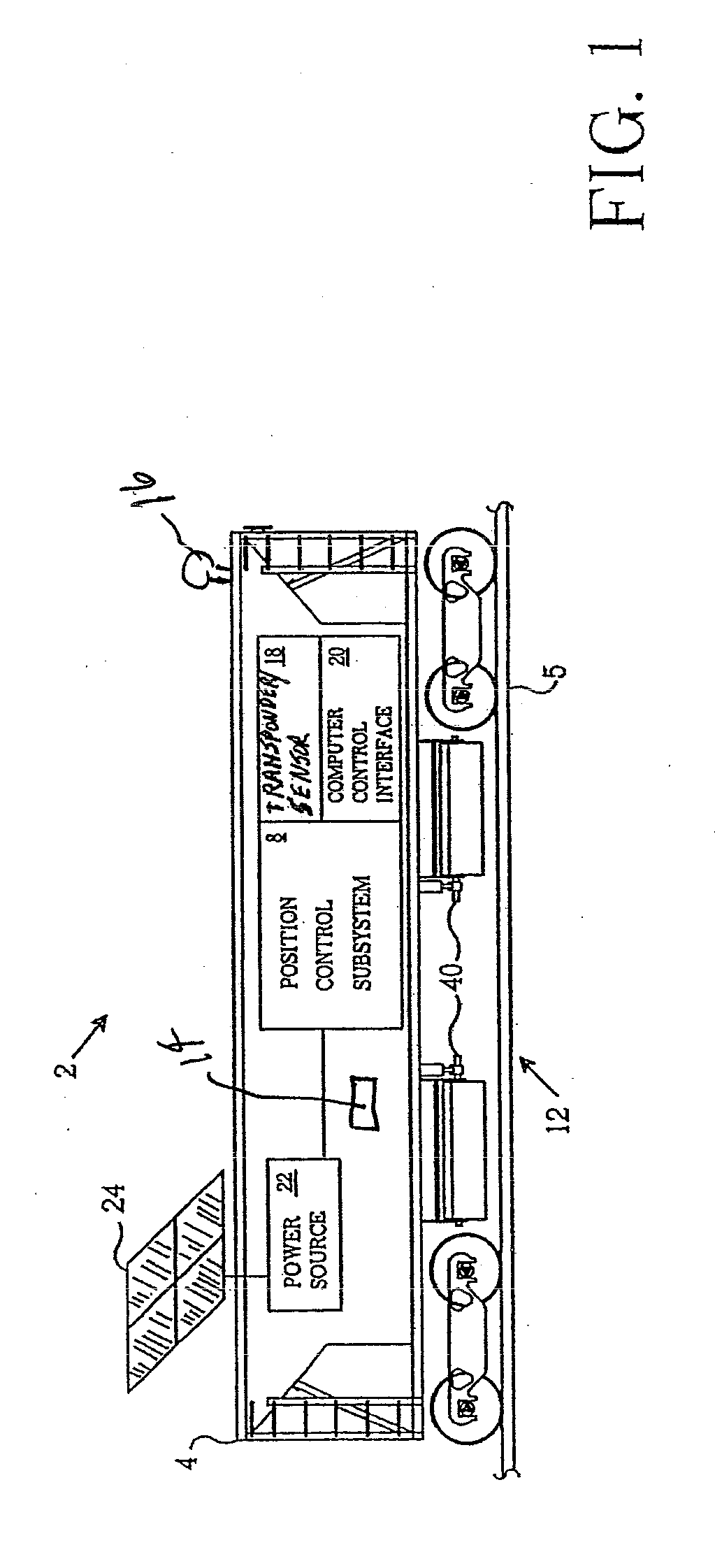
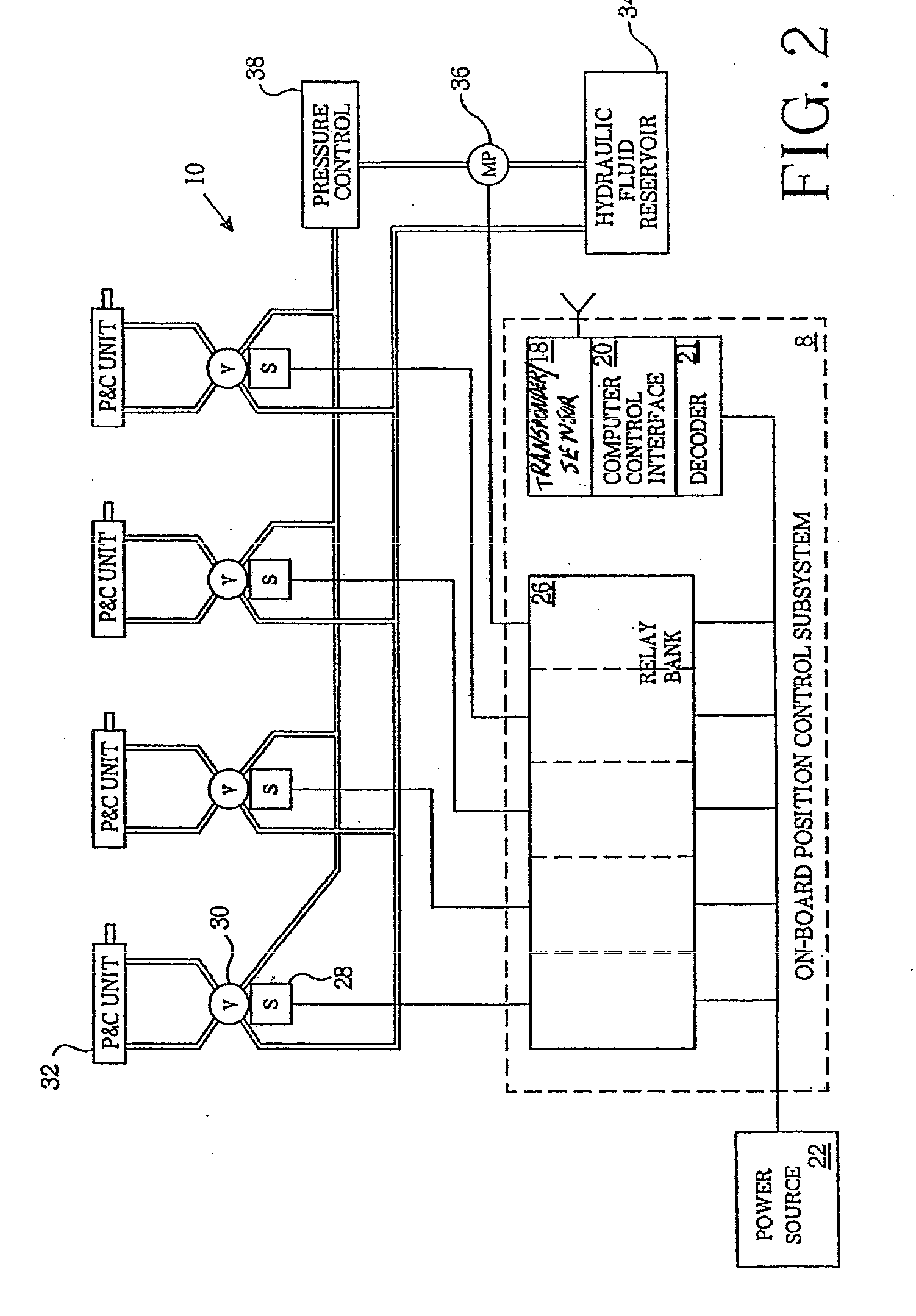
[0062] Referring to the drawings in more detail, the reference numeral 2 generally designates a railway ballast application system embodying the present invention. The system 2 is also referred to herein as a ballast spreading system. Without limitation on the generality of useful applications of the system 2, it is shown installed on a ballast train 3 (FIG. 14) including a plurality of ballast hopper cars 4 for ballast spreading operations.

[0063] The syst...


PUM


Abstract

A method and apparatus for spreading ballast along railways makes use of an inertial measurement system to determine where to apply ballast from a hopper car. A variety of techniques can be used to determine the location and speed of the ballast spreading train, including manual or automated visual techniques, laser technology, radar technology, radio frequency transponders, magnetic sensor, thermal imaging and aerial photogrammetry. The invention also contemplates “on the fly” surveys and terrain profiling using lasers or radar.

Description

CROSS-REFERENCE TO RELATED APPLICATIONS [0001] This application is a divisional of and claims priority to co-pending U.S. Patent Application Ser. No. 10 / 870,843, filed on Jun. 17, 2004, which application is hereby incorporated by reference to the extent permitted by applicable law. STATEMENT REGARDING FEDERALLY SPONSORED RESEARCH OR DEVELOPMENT [0002] Not applicable.BACKGROUND OF THE INVENTION [0003] Conventional railroads in the United States and elsewhere are typically formed by a compacted sub-grade, a bed of gravel ballast, wooden cross-ties positioned upon and within the ballast, and parallel steel rails secured to the ties. Variations of construction occur at road and bridge crossings and in other circumstances. The ballast beneath and between the ties stabilizes the positions of the ties, keeps the rails level, and provides some cushioning of the composite structure for loads imposed by rail traffic. Vibrations from the movement of tracked vehicles over the rails and weatheri...

Claims


Application Information

Patent Timeline
Patent Type & Authority Applications(United States)
IPC IPC(8): G05D1/00E01B27/02
CPCE01B27/02
Inventor HERZOG, STANLEY M.BOUNDS, IVAN E.SCHMITZ, RONPOGGLEMILLER, RANDYBEDINGFIELD, STEPHENLAUGHLIN, DANHARRIS, PATSHIRK, TONY
Owner HERZOG CONTRACTING
Learn More