
Artificial anterior chamber for use in keratoplasty

a technology for anterior chambers and keratoplasty, which is applied in the field of anterior chambers for keratoplasty, can solve the problems of significant salt solution leakage, difficult to ensure that the donor cornea is properly centred, etc., and achieve the effect of keeping the donor graft hydrated

Inactive Publication Date: 2007-06-07
WESTON PHILIP DOUGLAS
View PDF14 Cites 1 Cited by
  • Summary
  • Abstract
  • Description
  • Claims
  • Application Information

AI Technical Summary

Benefits of technology

[0010] According to a first aspect of the present invention, there is provided a device for retaining a donor cornea when cutting a donor button therefrom, the device comprising: a base unit having a hollow cylindrical pedestal projecting therefrom, the pedestal having a central axis and an end remote from the base unit defining an annular basal surface adapted to receive a donor cornea; means for visually indicating a position of the central axis of the pedestal; and removable retaining means adapted to fit snugly over the pedestal so as to retain the donor cornea securely in position on the end of the pedestal.
[0014] The provision of the cross-hairs allows a surgeon quickly and easily to ensure that a donor cornea is properly centred on the basal surface of the pedestal before (and during) positioning of the removable retaining means.
[0016] In particularly preferred embodiments, the base unit is hollow and is provided with an inlet for attachment to a liquid supply, for example a supply of balanced salt solution. The inlet may include a valve and be adapted for connection to a pipeline. Such inlets are often known as luer connectors. In use, the base unit, and hence the pedestal, can be filled with liquid so as to apply a precisely controlled fluid pressure to the underside of the donor corneal graft and thus give it a predetermined degree of curvature prior to cutting the button therefrom. Moreover, the liquid helps to keep the donor graft hydrated.

Problems solved by technology

In prior art punches, however, it can be difficult to ensure that the donor cornea is properly centred before cutting the donor button.
Moreover, when it is desired to keep the donor cornea flooded with a balanced salt solution during cutting of the button, there is often significant leakage of the salt solution.

Method used


Image

  • Artificial anterior chamber for use in keratoplasty
  • Artificial anterior chamber for use in keratoplasty

Examples


Embodiment Construction

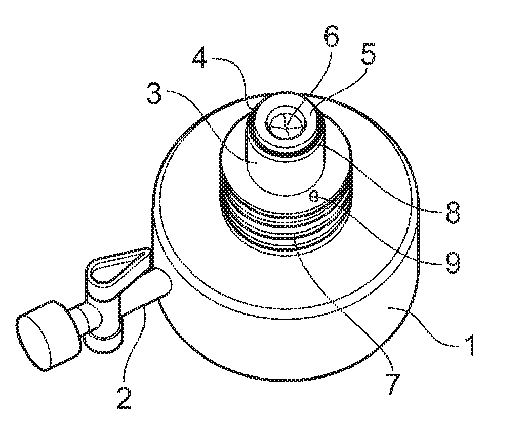
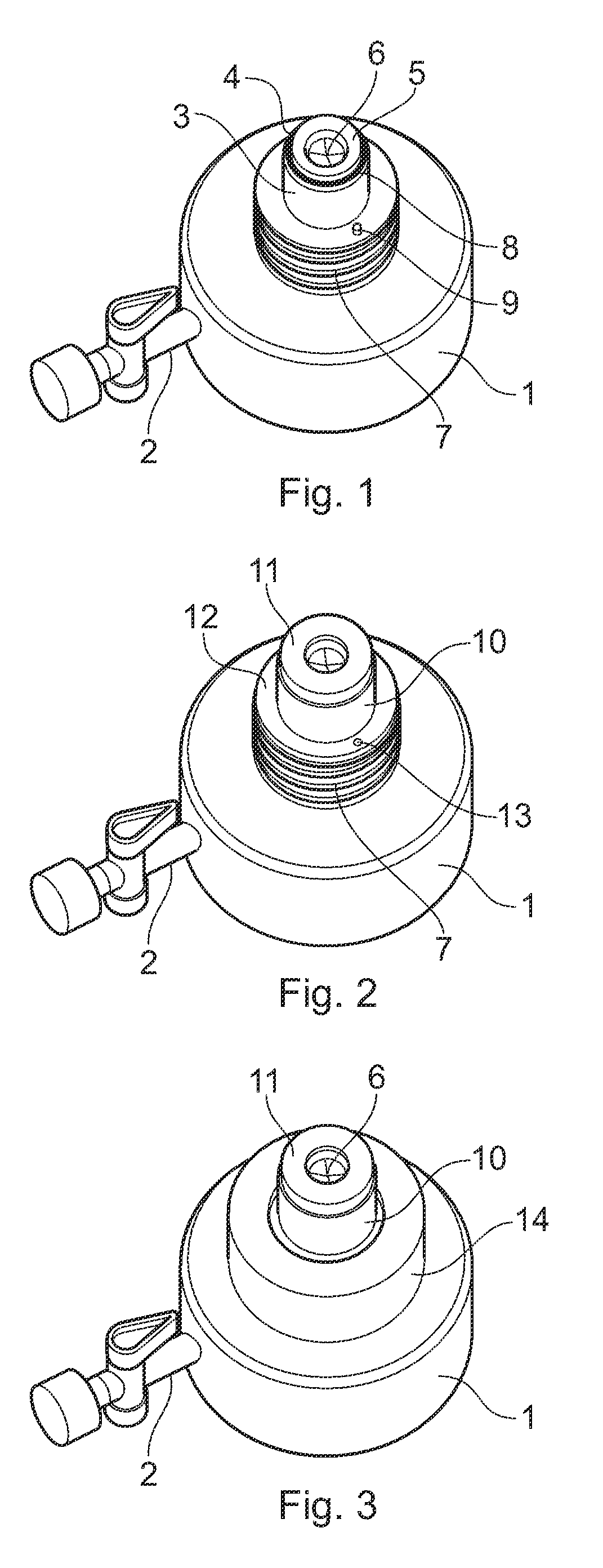
[0028]FIG. 1 shows a device of an embodiment of the present invention comprising a hollow, plastics moulded base unit 1 with a luer connection 2 for connection to a supply of balanced salt solution. A hollow, cylindrical pedestal 3 is integrally moulded with the base unit 1 and projects therefrom. The pedestal 3 has an end 4 remote from the base unit 1, which end 4 defines an annular basal surface 5 adapted to receive a donor cornea (not shown). The pedestal 3 is provided with cross-hairs 6 near its end 4, the cross-hairs 6 indicating the location of a central axis of the pedestal 3. The annular basal surface is provided with a silicone O-ring seal 8 about its periphery. A screw thread 7 is provided at a base of the pedestal 3, and an alignment peg 9 is also provided at the base.

[0029]FIG. 2 shows a removable, cylindrical retaining collar 10 mounted on the pedestal 3. The collar 10 has an inwardly-facing flange 11 at its upper end, and an outwardly-facing flange 12 at its lower end...


PUM


Abstract

There is disclosed a device for retaining a donor cornea when cutting a donor button. The device comprises a base unit having a hollow cylindrical pedestal projecting therefrom, the pedestal having a central axis and an end remote from the base unit defining an annular basal surface adapted to receive a donor cornea. There may be provided cross-hair means for visually indicating a position of the central axis of the pedestal, and removable retaining means adapted to fit snugly over the pedestal so as to retain the donor cornea securely in position on the end of the pedestal.

Description

CROSS-REFERENCE TO RELATED APPLICATIONS [0001] Priority of U.K. Patent Application No. 0524965.1, filed 7 Dec. 2005, incorporated herein by reference, is hereby claimed. STATEMENT REGARDING FEDERALLY SPONSORED RESEARCH OR DEVELOPMENT [0002] Not applicable. REFERENCE TO A “MICROFICHE APPENDIX”[0003] Not applicable. BACKGROUND OF THE INVENTION [0004] 1. Field of the Invention [0005] The present invention relates to an anterior chamber for use in keratoplasty, and in particular to a device adapted for facilitating the cutting of a donor button from the epithelial surface of a donor cornea harvested from a cadaver. [0006] 2. General Background of the Invention [0007] In the field of eye surgery, it is sometimes necessary to perform a corneal transplant by replacing a diseased or damaged cornea of a patient with a donor cornea harvested from an immunologically compatible cadaver. This is generally achieved by removing at least a central portion of the diseased or damaged cornea from a pa...

Claims


Application Information

Patent Timeline
Patent Type & Authority Applications(United States)
IPC IPC(8): A61F9/00
CPCA01N1/02A01N1/0263A61F2/0095A61F2/14A61F2/142A61F9/007A61F9/0133
Inventor WESTON, PHILIP DOUGLAS
Owner WESTON PHILIP DOUGLAS
Learn More