
Stereo-examination systems and stereo-image generation apparatus as well as a method for operating the same

a technology of stereo-image generation and stereo-examination system, which is applied in the field of stereo-examination system, can solve problems such as obstructive spatial limitation

Inactive Publication Date: 2007-06-07
CARL ZEISS SURGICAL
View PDF17 Cites 18 Cited by
  • Summary
  • Abstract
  • Description
  • Claims
  • Application Information

AI Technical Summary

Benefits of technology

[0007] Accordingly, it is an object of the present invention to provide a stereo-examination system and a stereo-image generation apparatus which provide degrees of freedom at least for one observer as regards his position relative to the object to be viewed.
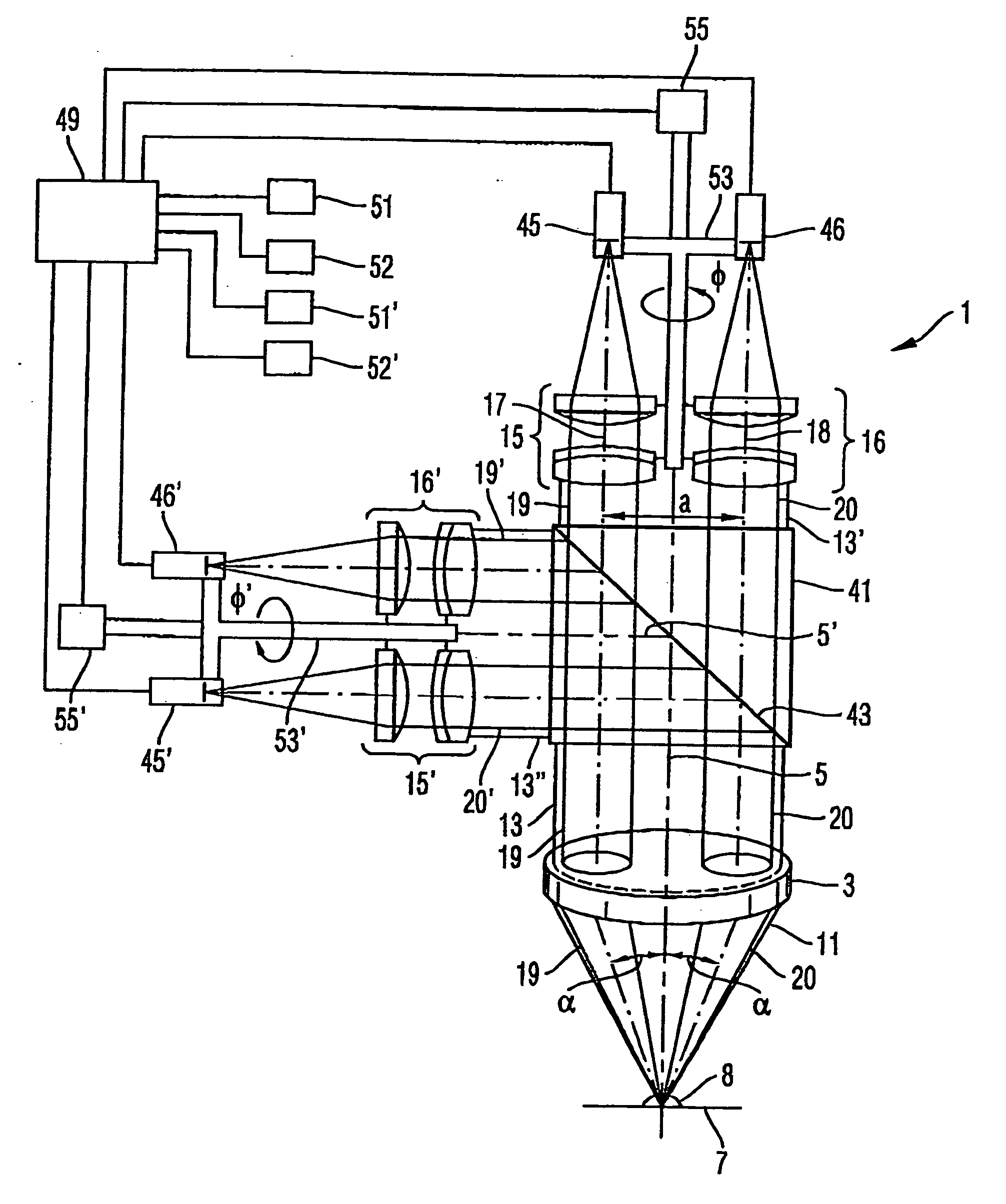
[0010] To this end, the stereo-examination system comprises a controller for controlling the selection arrangement such that it displaces the beam cross-section of the at least one partial beam bundle relative to the beam cross-section of the image-side beam bundle in circumferential direction about the optical axis. As a result, it is possible to eliminate and modify the fixed arrangement, as it is known from the prior art, of the fed-out partial beam bundle in circumferential direction about the optical axis of the object such that representations of the object can be supplied to the observer via the displaced partial beam bundles, said representations being generated from different, variable viewing angles. It is thus possible for the observer to move in azimuthal direction about the object and, when the selection arrangement is controlled accordingly, to view stereoscopic images of the object at different azimuth angles.
[0011] Preferably, the selection arrangement is provided to selectively choose only a first one or a second one of the pair of partial beam bundles from the image-side beam bundle. As a result, the individual partial beam bundles can be imaged, successively in time, by the image transmission apparatus. It is thus particularly easy to spatially separate the individual partial beam bundles from each other. This applies, in particular, if several pairs of partial beam bundles are fed out of the image-side beam cross-section for several observers.
[0025] If use is made of a beam-dividing arrangement, it offers a simple possibility to illuminate the object in that an illuminating light beam is fed into the beam path through the beam-dividing arrangement such that the illuminating light beam passes through the objective and is focused by the same onto the object.

Problems solved by technology

In particular, if the microscope is used as surgical microscope during a surgical operation, this spatial limitation is obstructive for the two observers who must operate as surgeons in the operating field.

Method used


Image

  • Stereo-examination systems and stereo-image generation apparatus as well as a method for operating the same
  • Stereo-examination systems and stereo-image generation apparatus as well as a method for operating the same
  • Stereo-examination systems and stereo-image generation apparatus as well as a method for operating the same

Examples


Embodiment Construction

[0055] The system and the method according to the invention serve to generate stereoscopic images and representations, respectively, of an object such that, when viewing the images, the observer obtains a three-dimensional impression of the object. To this end, it is required for the left eye and the right eye of the observer to perceive different images from different directions of view onto the object.

[0056] An embodiment of a stereo-examination system according to the invention is schematically shown in FIG. 3. The stereo-examination system 1 comprises an objective 3 with an optical axis 5 and an object plane 7. An object 8 is positionable in the object plane 7. An object-side beam bundle 11 emanates from the object 8 or object plane 7 into a solid angle region 9 and is received by the objective 3 to be imaged to infinity and converted into a parallel image-side beam bundle 13, respectively, the optical axis 5 being disposed in a center of a beam cross-section of the image-side ...


PUM


Abstract

A stereo-examination system for imaging an object 8 is proposed, comprising an objective arrangement 3 having an optical axis 5 and an object plane 7 for positioning the object 8 to be imaged, wherein the objective arrangement 3 receives an object-side beam bundle 11 emanating from the object plane 7 into a solid angle region 9 and converts the same into an image-side beam bundle 13, a selection arrangement for selecting at least a pair of partial beam bundles 19, 20 from the image-side beam bundle 13, and an image transmission apparatus 51, 52 for generating a representation of images of the object 8 provided by the partial beam bundles 19, 20. The stereo-examination system is distinguished in that the selection arrangement is provided for displacing a beam cross-section of at least one of the two partial beam bundles 19, 20 relative to a beam cross-section of the image-side beam bundle 13, a controller 49 being provided for controlling the selection arrangement to displace the beam cross-section of the at least one partial beam bundle 19, 20 in circumferential direction about the optical axis 5.

Description

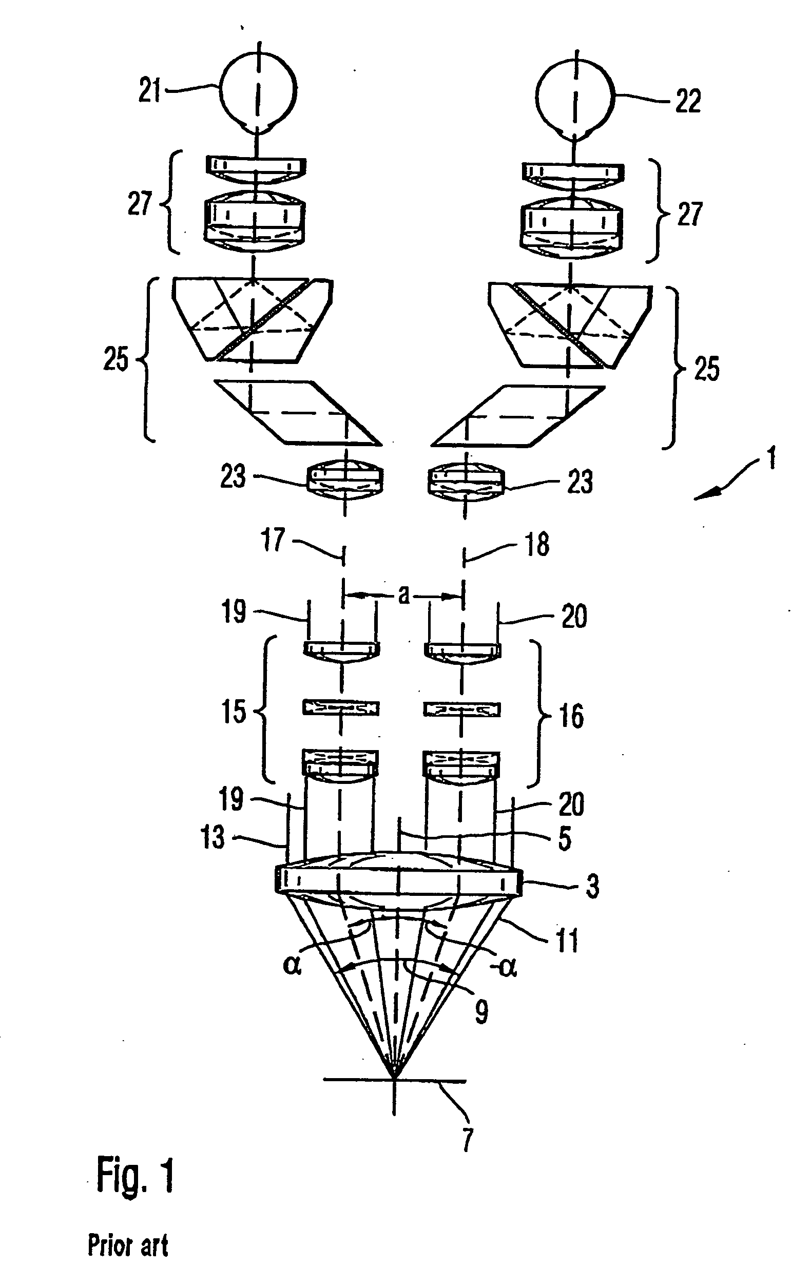
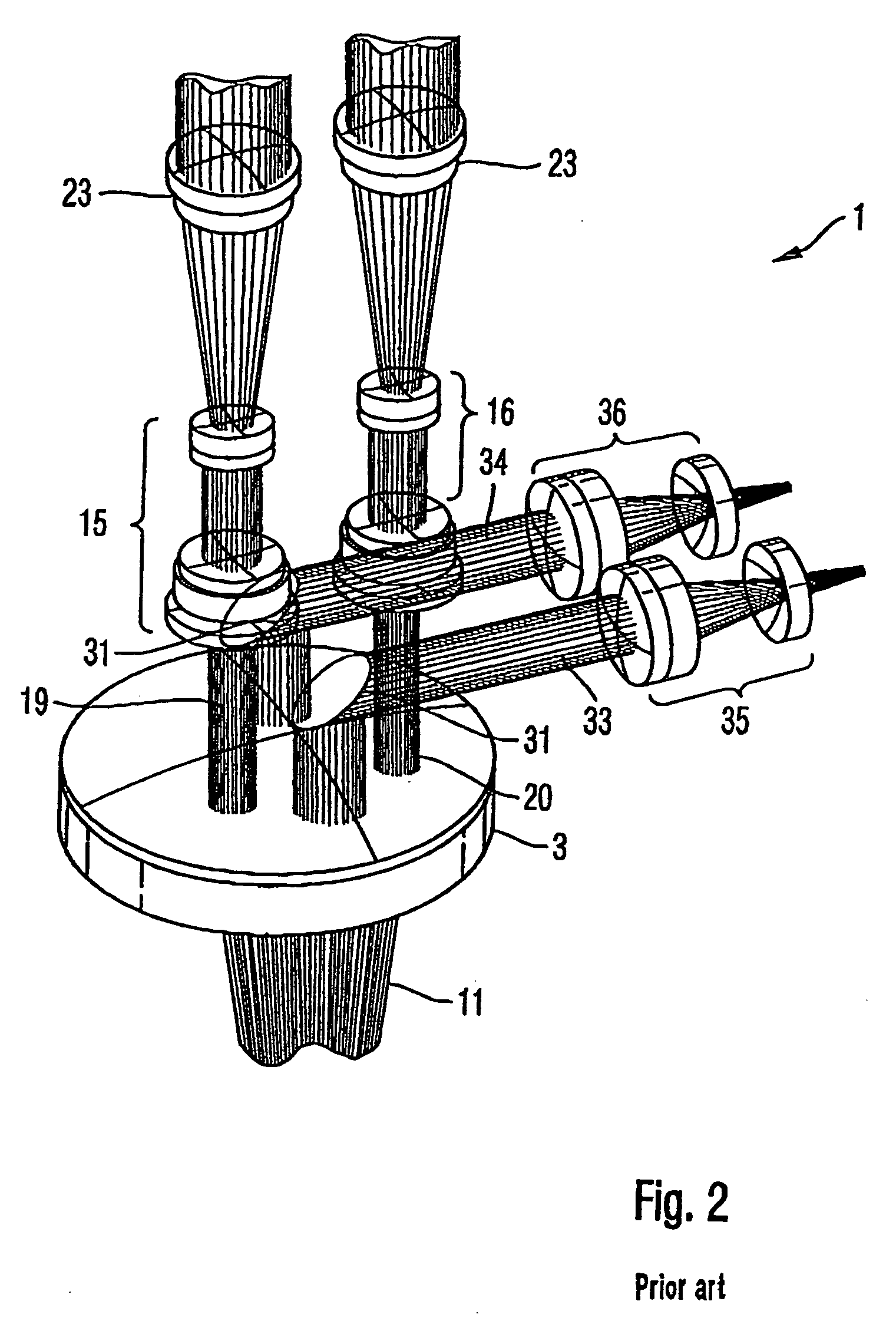
CROSS REFERENCE TO RELATED APPLICATIONS [0001] This application is a divisional of U.S. patent application Ser. No. 10 / 357,260, filed Feb. 3, 2003, which claims priority from Germany Patent Applications No. 102 04 431.7, filed Feb. 4, 2002, and No. 103 00 925.6, filed Jan. 13, 2003, the contents of which are incorporated herein by reference.FIELD OF THE INVENTION [0002] The invention relates to a stereo-examination system for imaging an object, a stereo-image generation apparatus for generating at least a pair of images of an object and a method for generating such images. BACKGROUND OF THE INVENTION [0003] An example of a conventional stereo-examination system is a stereomicroscope. A beam path of a conventional stereomicroscope is schematically shown in FIG. 1. The stereomicroscope 1 shown there comprises an objective 3 with an optical axis 5 and an object plane 7 in which an object to be viewed is positioned. A beam bundle 11 emanating from the object or object plane 7 into a sol...

Claims


Application Information

Patent Timeline
Patent Type & Authority Applications(United States)
IPC IPC(8): G02B21/22G01B11/24G01B11/245G02B27/22
CPCG02B21/22
Inventor HAUGER, CHRISTOPHHAISCH, MICHAELOBREBSKI, ANDREAS
Owner CARL ZEISS SURGICAL
Learn More