Paint circulation system with coiled back pressure regulator

a circulation system and regulator technology, applied in the direction of superimposed coating process, liquid/solution decomposition chemical coating, separation process, etc., can solve the problems of large amount of paint shear produced by the regulator, reducing the percentage of demand on other colors, and reducing color usage correspondingly increasing the paint residence time in the circulation system. , to achieve the effect of reducing paint shear in the paint circulation system

Inactive Publication Date: 2007-05-31
FORD MOTOR CO
View PDF13 Cites 6 Cited by
  • Summary
  • Abstract
  • Description
  • Claims
  • Application Information

AI Technical Summary

Benefits of technology

[0008] Accordingly, the present invention is an apparatus and method for reducing paint shear in paint circulation systems. The apparatus includes a paint reservoir, a circulation pump and a paint supply conduit delivering paint to a paint supply manifold. A paint return manifold and paint return conduit return paint to the paint reservoir. A back pressure regulator located in the paint return conduit between the paint return manifold and paint reservoir operates to control the system pressure. The back pressure regulator includes a tube having a length sufficient to achieve a predetermined pressure drop while maintaining laminar flow.

Problems solved by technology

Such regulators, however, produce a large amount of paint shear as the continuous flow of paint is taken from a high pressure to a low pressure in a very short distance.
One drawback of increasing available colors is that there is a lower percentage of demand on the other colors.
Accordingly, reduced color usage correspondingly increases paint residence time in the circulation system.
Shear degradation is most apparent in short circulation systems local to the booths that are designed to offer special order or low-volume colors.
Pigments and mica flakes in metal paints will deform or degrade over time when subjected to shear stress resulting in a less consistent paint appearance and the potential for increased replenishment of paint and scrap paint.

Method used


Image

  • Paint circulation system with coiled back pressure regulator
  • Paint circulation system with coiled back pressure regulator
  • Paint circulation system with coiled back pressure regulator

Examples


Embodiment Construction

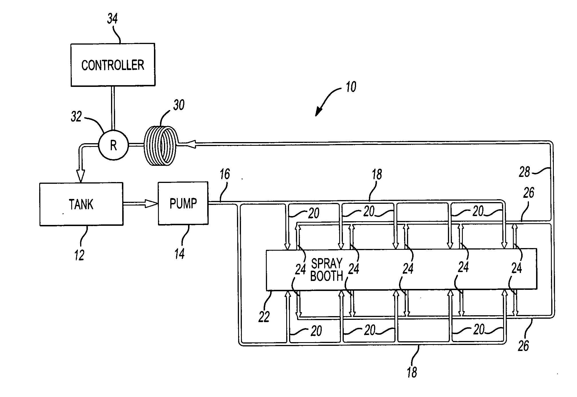
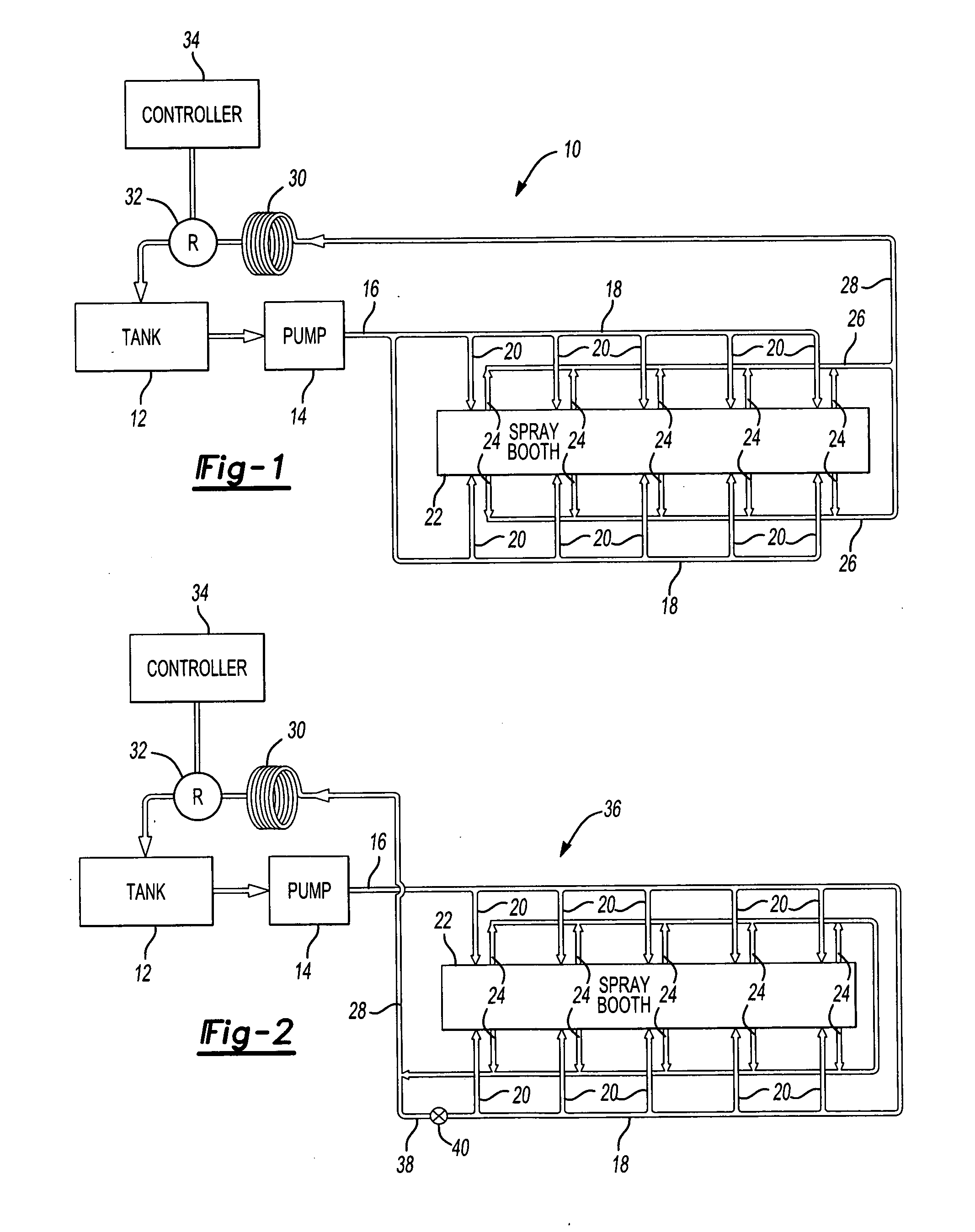
[0016] Referring now to the drawings, FIG. 1 illustrates a parallel paint circulation system, seen generally at 10, according to the present invention. The paint circulation system 10 typically includes a paint reservoir or tank 12. A pump 14 supplies paint from the reservoir 12 through a paint supply conduit 16 to a paint supply header 18. A plurality of supply drop lines 20 connected to the paint supply header 18 supply paint to a paint station (not shown) having a paint applicator such as a spray gun or rotary bell used to apply paint to a workpiece in the spray booth 22. A plurality of return drop lines 24 connected to the paint station return the unused paint to a paint return header 26. A paint return conduit 28 returns the paint through a first back pressure regulator 30. A second back pressure regulator 32 operated by a controller 34 provides an additional means to control the flow of the paint circulating through the system 10.

[0017]FIG. 2 illustrates a pressure differenti...


PUM

PropertyMeasurementUnit
lengthaaaaaaaaaa
pressure dropaaaaaaaaaa
inner diameteraaaaaaaaaa

Abstract

A paint circulation system for use in painting a workpiece. The paint circulation system operates to deliver paint to a paint applicator placed adjacent a workstation such as a paint spray booth. The paint is continuously circulated through the system and is return to a paint reservoir through a paint return conduit. A coiled tube back pressure regulator located on the paint return conduit between the paint return manifold and paint reservoir functions to achieve a desired pressure drop in the paint circulation system while reducing paint shear and degradation typically associated with conventional pressure regulators.

Description

CROSS-REFERENCE TO RELATED APPLICATIONS [0001] Not Applicable BACKGROUND OF THE INVENTION [0002] 1. Field of the Invention [0003] The present invention relates to a paint circulation system; and, more specifically, to a paint circulation system including a coiled back pressure regulator. [0004] 2. Description of Related Art [0005] Modern manufacturing processes, including those used for automotive vehicles, typically utilize a paint circulation system capable of delivering a multitude of paint colors at the same time. Each color requires a separate distribution system including a network of supply and return lines, a plurality of paint applicators, such as spray guns or rotary bells and a circulation pump that operates to continuously circulate the paint within the system. The system also includes a back pressure regulator that operates to control pressure and fluid flow through the circulation system. Manual and automatic paint applicators require controlled fluid pressure and flow...

Claims


Application Information

Patent Timeline
Patent Type & Authority Applications(United States)
IPC IPC(8): B05D1/40B05D1/02B05C5/00
CPCB05B15/1225B05B14/40Y10T137/86075
Inventor JONES, MICHAEL
Owner FORD MOTOR CO
Why Eureka
Try Eureka