
Digital television transmitter/receiver and method of processing data in digital television transmitter/receiver

a digital television and transmitter/receiver technology, applied in the field of digital communication systems, can solve the problems of reducing the reception performance of the conventional atsc vsb reception system, and achieve the effects of enhancing reception performance, supplemental data transmission, and robust against nois

Inactive Publication Date: 2007-05-31
LG ELECTRONICS INC
View PDF8 Cites 298 Cited by
  • Summary
  • Abstract
  • Description
  • Claims
  • Application Information

AI Technical Summary

Benefits of technology

[0012] An object of the present invention is to provide a digital television (DTV) transmitter and a method of coding main and enhanced data in the DTV transmitter, by which a new digital broadcast system suitable for supplemental data transmission and robust against noise can be provided.
[0013] Another object of the present invention is to provide a digital television (DTV) transmitter and a method of coding main and enhanced data in the DTV transmitter, by which reception performance can be enhanced by transmitting data known by a transmitting / receiving side in a manner of inserting the known data in a prescribed area of a data section.
[0014] A further object of the present invention is to provide a digital television (DTV) transmitter and a method of coding main and enhanced data in the DTV transmitter, by which various transmission parameters for a transmitted signal can be efficiently transmitted and received.

Problems solved by technology

Yet, in case of supplemental data (e.g., a program execution file, stock information, etc.), a 1-bit error can cause a serious problem.
However, in a poor channel environment, reception performance of the conventional ATSC VSB reception system may be reduced.

Method used


Image

  • Digital television transmitter/receiver and method of processing data in digital television transmitter/receiver
  • Digital television transmitter/receiver and method of processing data in digital television transmitter/receiver
  • Digital television transmitter/receiver and method of processing data in digital television transmitter/receiver

Examples


first embodiment

Case of Inserting Transmission Parameter in Field Sync Segment Area

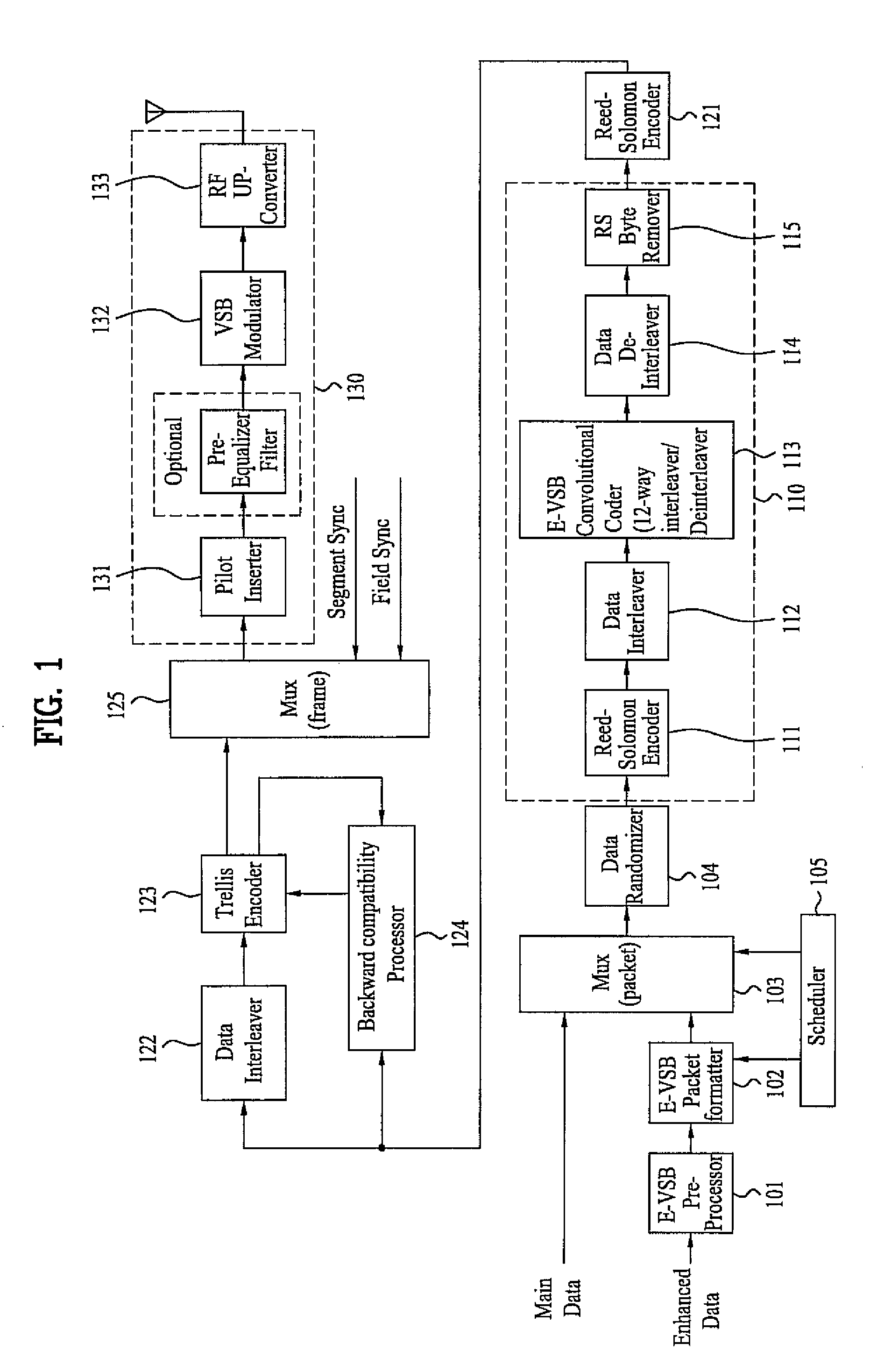
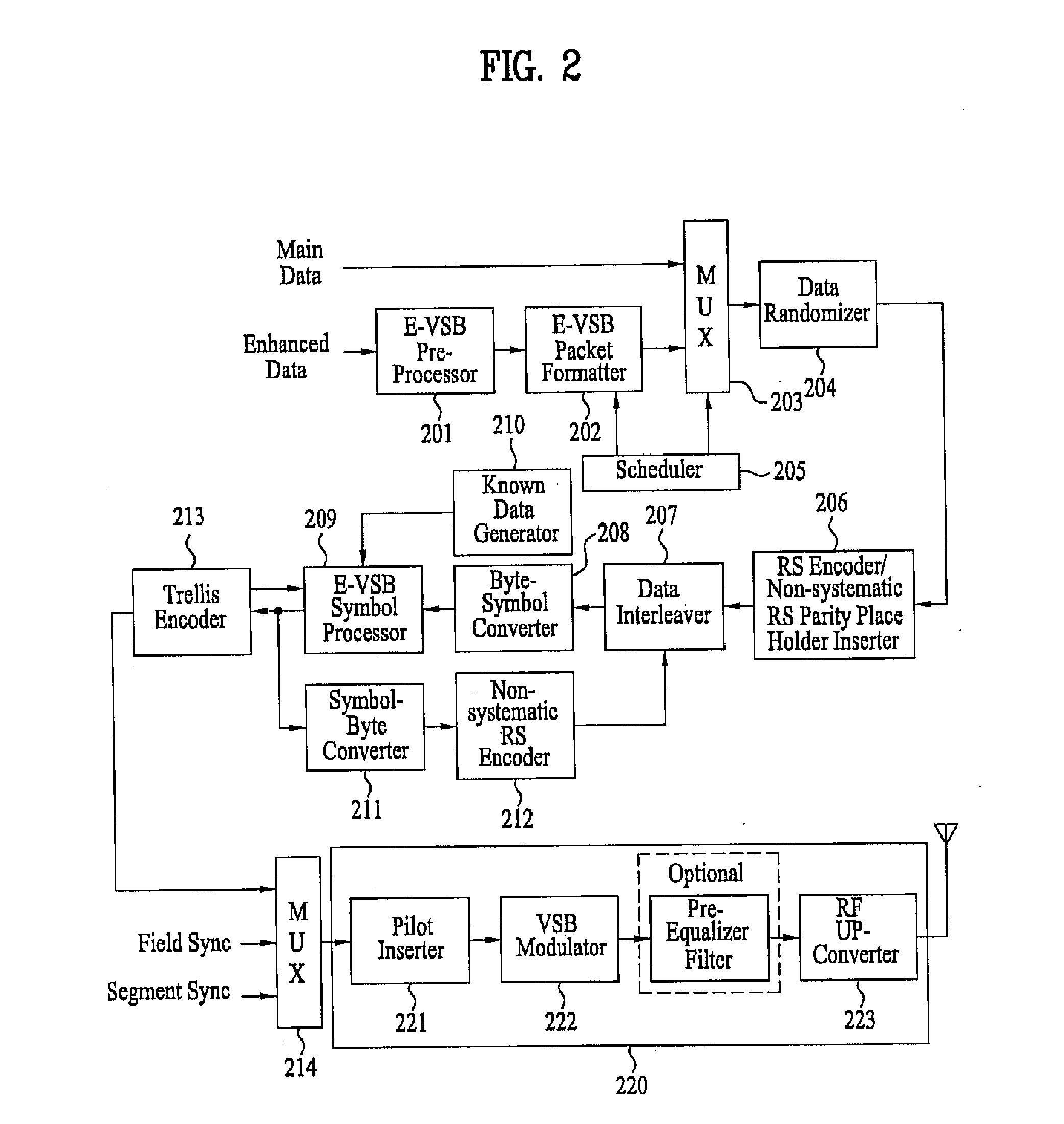
[0062]FIG. 3 is a detailed block diagram of the frame multiplexer (125 or 214) shown in FIG. 1 or FIG. 2 according to one embodiment of the present invention to transmit a transmission parameter by inserting the transmission parameter in a field sync segment.

[0063] Referring to FIG. 3, the frame multiplexer includes a first multiplexer 301 multiplexing a field sync signal and a transmission parameter and a second multiplexer 302 multiplexing an E-VSB data symbol, a segment sync signal and an output of the first multiplexer 301 to output.

[0064] A VSB frame generally consists of two fields and each of the fields consists of one field sync segment and 312 data segments. Each of the data segments consists of total 832 symbols. In this case, first four symbols of one data segment corresponds a segment sync part and a first segment of one field corresponds to a field sync part.

[0065] One field sync signal consists of o...

second embodiment

Case of Inserting Transmission Parameter in E-VSB Packet Formatter

[0070]FIG. 4 is a detailed block diagram of the E-VSB packet formatter (102, 202) shown in FIG. 1 or FIG. 2 according to one embodiment of the present invention to transmit a transmission parameter by inserting the transmission parameter in a group.

[0071] Referring to FIG. 4, the E-VSB packet formatter includes an enhanced data formatter 401, a know data generator 402, a transmission parameter generator 403, a multiplexer 404 and an MPEG TS packetizer 405.

[0072] If enhanced data is inputted from the E-VSB pre-processor, the enhanced data formatter 401 aligns the enhanced data within a group and then outputs the aligned data to the multiplexer 404.

[0073] And, the known data generator 402 generates known data and then outputs the generated data to the multiplexer 404 as well.

[0074] If the E-VSB packet formatter is applied to FIG. 1, the known data generator 402 is able to practical known data or a known data place ...

third embodiment

Case of Inserting Transmission Parameter in Symbol Domain

[0080]FIG. 5 is a detailed block diagram of the convolutional coder (113) of the transmitting system shown in FIG. 1 according to one embodiment of the present invention to transmit a transmission parameter by multiplexing the transmission parameter with a data symbol and known data in a symbol domain.

[0081] Referring to FIG. 5, the convolutional coder includes a byte-to-symbol converter or 12-way interleaver 501, a known data generator 502, a transmission data generator 503, a first multiplexer 504, a second multiplexer 505, an E-VSB symbol processor 506 and a symbol-to-byte converter or 12-way deinterleaver 507.

[0082] In this case, the E-VSB packet formatter shown in FIG. 1 determines a known data place holder in which known data will be inserted, inserts null data in the determined data place holder and then multiplexes it with enhanced data pre-processed by the E-VSB pre-processor, for example.

[0083] The byte-to-symbol...


PUM


Abstract

A digital television (DTV) transmitter and a method of processing data in the DTV transmitter / receiver are disclosed. In the DTV transmitter, a pre-processor pre-processes the enhanced data by coding the enhanced data for forward error correction (FEC) and expanding the FEC-coded data. A packet formatter generates one or more groups of enhanced data packets, each enhanced data packet including the pre-processed enhanced data and known data, wherein the data formatter adds burst time information into each group of enhanced data packets. And, a packet multiplexer generates at least one burst of enhanced data by multiplexing the one or more groups of enhanced data packets with at least one main data packet including the main data, each burst of enhanced data including at least one group of enhanced data packets.

Description

[0001] This application claims the benefit of the Korean Patent Application No. 10-2005-0113464, filed on Nov. 25, 2005, which is hereby incorporated by reference as if fully set forth herein. BACKGROUND OF THE INVENTION [0002] 1. Field of the Invention [0003] The present invention relates to a digital communication system, and more particularly, to a digital television (DTV) transmitter / receiver and a method of processing data in the DTV transmitter / receiver. Although the present invention is suitable for a wide scope of applications, it is particularly suitable for transmitting and receiving digital broadcasts. [0004] 2. Discussion of the Related Art [0005] Generally, the 8T-VSB transmission system adopted as a digital broadcasting standard by Korea and North America is a digital broadcast system developed for MPEG video / audio data transmission. [0006] As the digital signal processing technology rapidly develops with the global use of Internet, the tendency for combining digital h...

Claims


Application Information

Patent Timeline
IPC IPC(8): H04J3/04H04N7/24H04N19/89H04N21/2383H04N21/438
CPCH04N21/234327H04N21/235H04N21/2383H04N21/4305H04N21/435H04N21/4382H04N7/015
Inventor KANG, KYUNG WONKWAK, KOOK YEONKOO, JA HYUKSHIN, KYUNG WOOKSUH, YONG HAKHONG, YOUNG JINHONG, SUNG RYONG
Owner LG ELECTRONICS INC
Learn More