Shield arrangement for a vacuum cell

a vacuum cell and shield technology, applied in the direction of fluid pressure measurement, fluid pressure measurement by electric/magnetic elements, instruments, etc., can solve the problems of contaminating the vacuum sensor, imprecise or error measurements or pressure indications, and error measurements, so as to reduce the contamination of the vacuum cell and increase the service life of the measuring cell significantly. , the effect of reducing the disadvantages of prior ar

Active Publication Date: 2007-05-31
INFICON HLDG AG
View PDF13 Cites 15 Cited by
  • Summary
  • Abstract
  • Description
  • Claims
  • Application Information

AI Technical Summary

Benefits of technology

[0003] The present invention has as its aim eliminating the disadvantages of prior art. The aim of the present invention is in particular realizing a shield arrangement for vacuum cells, in particular for diaphragm measuring cells, which drastically decreases the contamination of t

Problems solved by technology

One problem encountered herein is that the process gas, but also residual gas components, may contaminate the vacuum sensor during the process.
Consequently, imprecise or error measurements or pressure indications, may herein result.
Contaminations of this thin diaphragm, for example with gas and/or with particles, can lead to tensile and/or pressure stress, which additionally affects the deformation of the diaphragm and subsequently leads to error measurements, for example in the absolute values to be measured, or to u

Method used


Image

  • Shield arrangement for a vacuum cell
  • Shield arrangement for a vacuum cell
  • Shield arrangement for a vacuum cell

Examples


Embodiment Construction

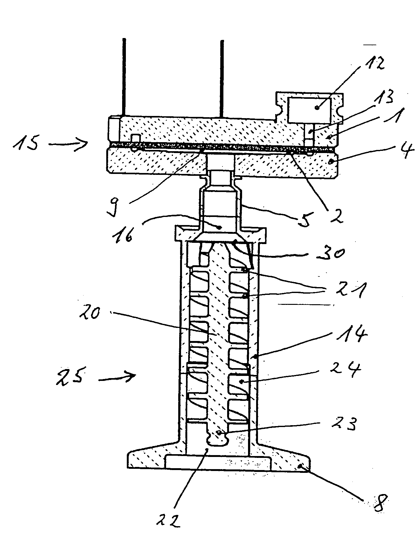
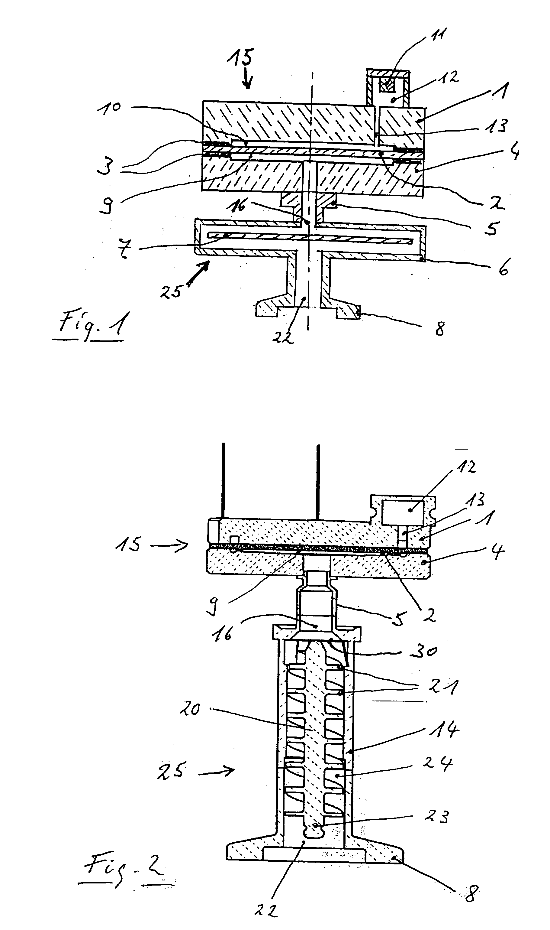
[0015]FIG. 2 shows in cross section a vacuum measuring cell arrangement according to the invention with a diaphragm vacuum measuring cell 15 and an inventive shield arrangement 25 disposed thereon with a screw shield 20, which is implemented as a spiral-form shield or as helical shield. The vacuum measuring cell 15 is comprised of a first flat round housing part 1 and a second round flat housing part 4, a diaphragm 2 being disposed between them such that it forms a sealing at the periphery. With respect to the first housing part 1 the diaphragm 2 is disposed at such a slight spacing that between them a reference vacuum space is formed, which, via an interconnection 13, is comprised with a getter space 12 for maintaining a reference vacuum. On the opposite diaphragm side between the diaphragm 2 and the second housing part 4 is formed a measuring vacuum space 9, which preferably in the center communicates through the second housing part 4 via an opening and a connection fitting 5 with...


PUM

PropertyMeasurementUnit
Lengthaaaaaaaaaa
Diameteraaaaaaaaaa
Proximity effectaaaaaaaaaa

Abstract

A shield arrangement for a vacuum measuring cell has a tubular shield housing encompassing a shield and an exit port for connection to a vacuum measuring cell and a connection opening for the object space to be measured. The shield is between the two openings and is implemented as a screw shield with spiral convolutions, its thread flange in the outer diameter being in contact on the inner wall of the shield housing such that a gas throughflow between the outer diameter of the thread flange and the inner wall is inhibited and is substantially forced into the spiral thread flight, and the exit port is on one side of the tubular section and the connection opening is on the other, opposite side and the screw shield is implemented such that in the axial line of vision the shield arrangement between the two openings is optically tight.

Description

FIELD AND BACKGROUND OF THE INVENTION [0001] The invention relates to a shield arrangement for a vacuum cell. [0002] Total vacuum cells are utilized to measure the total pressure in vacuum chambers. The vacuum measuring cells are employed when monitoring various vacuum processes. Typical vacuum processes are here surface treatment processes, such as for example coating methods and etching methods. Such methods operate for example in the pressure ranges of 10−5 mbar up to 100 mbar. It is conventional to measure such pressure ranges using so-called Pirani vacuum measuring cells or with so-called diaphragm vacuum measuring cells. One problem encountered herein is that the process gas, but also residual gas components, may contaminate the vacuum sensor during the process. Consequently, imprecise or error measurements or pressure indications, may herein result. The vacuum measuring cells exhibit a drift behavior, corresponding to the time during which they are exposed to the process, whi...

Claims


Application Information

Patent Timeline
IPC IPC(8): G01L21/30
CPCC23C14/54C23C16/45557G01L21/00G01L19/0007G01L19/0609G01L9/0072G01L21/24G01L19/00
Inventor BJORKMAN, PERWALCHLI, URSHANSELMANN, HANSJAKOBDURIS, STANISLAVWUEST, MARTIN
Owner INFICON HLDG AG
Why Eureka
Try Eureka