Axial current interrupter

a current interrupter and circuit arc technology, applied in the direction of air-break switches, high-tension/heavy-dress switches, electrical equipment, etc., can solve the problem of corresponding rapid interruption of curren

Inactive Publication Date: 2007-05-31
GENERAL ELECTRIC CO
View PDF13 Cites 11 Cited by
  • Summary
  • Abstract
  • Description
  • Claims
  • Application Information

AI Technical Summary

Problems solved by technology

The voltage investment in an arc may be made to rise very quickly to cause a corresponding rapid interruption of the current.

Method used


Image

  • Axial current interrupter
  • Axial current interrupter
  • Axial current interrupter

Examples


Embodiment Construction

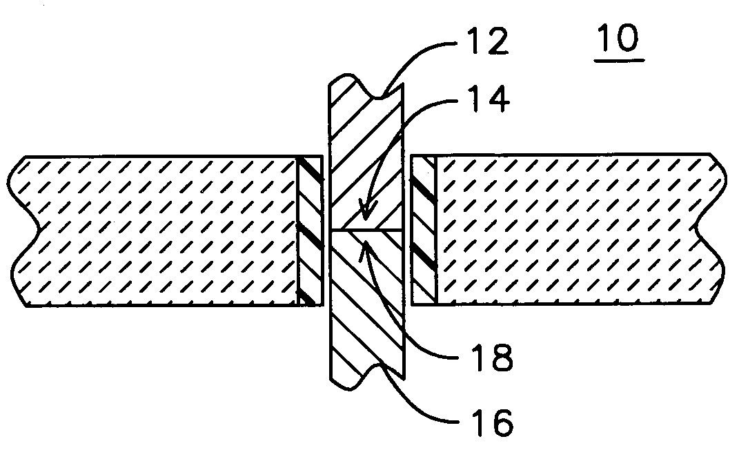
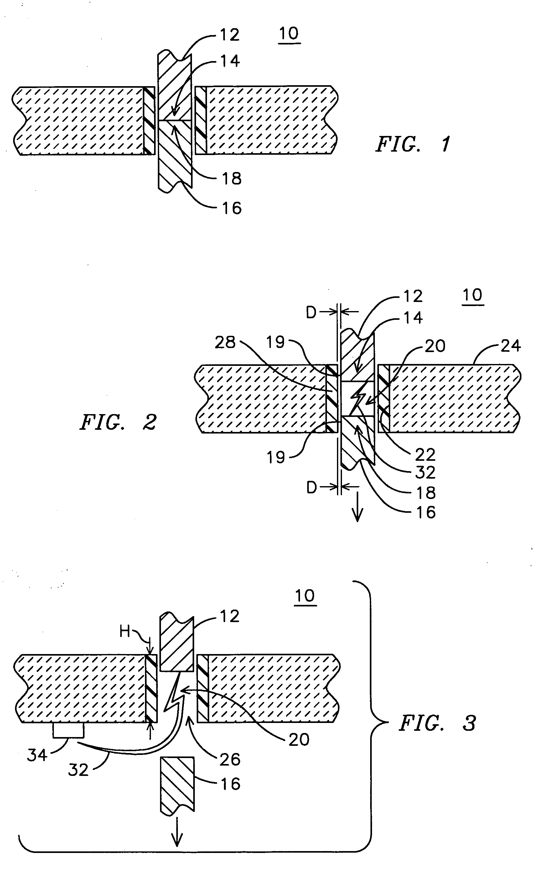
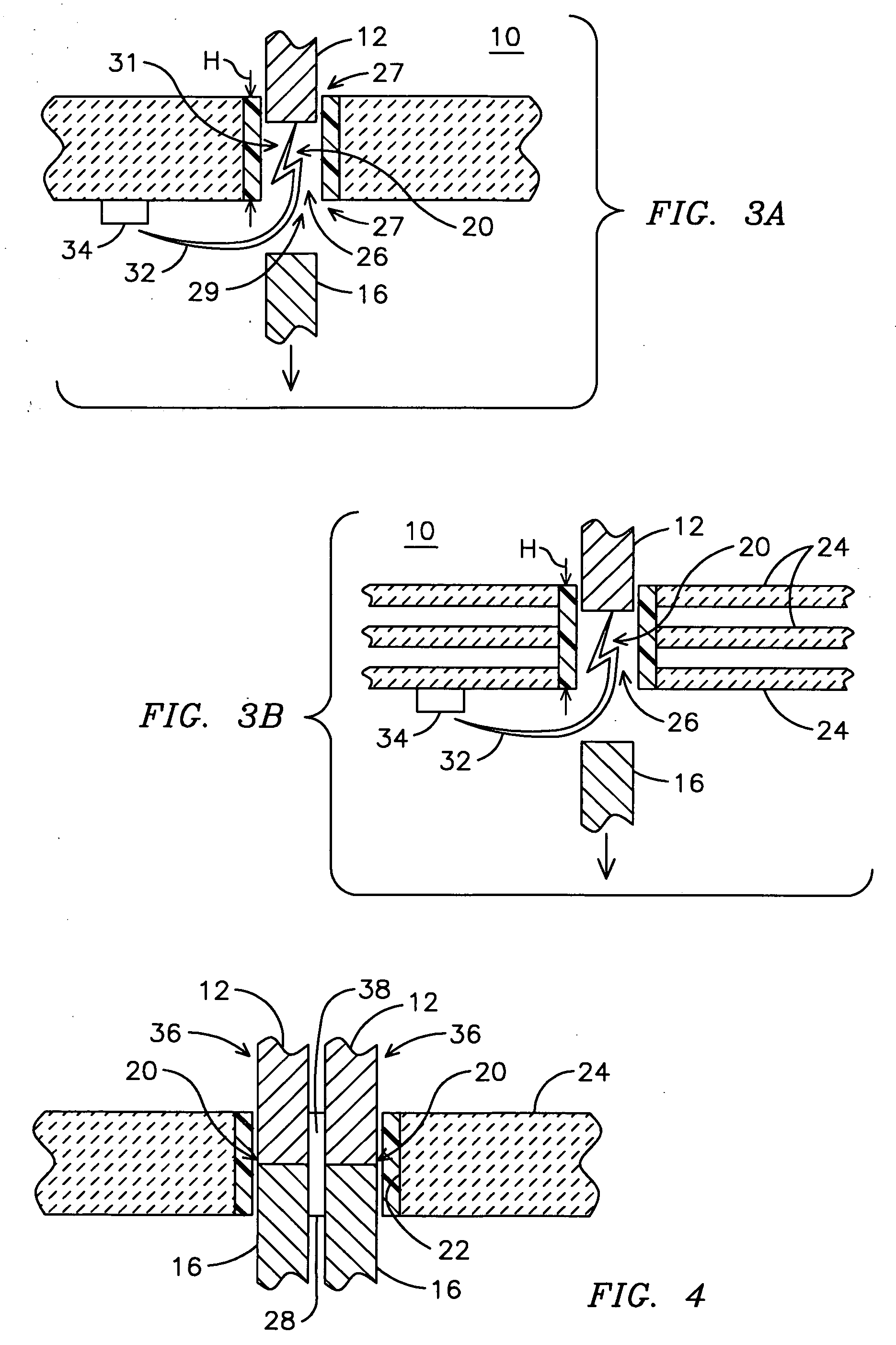
[0016] The inventors of the present invention have innovatively realized that a portion of the energy in an arc produced in a circuit interrupter may be harnessed to provide a force acting to separate contacts of the circuit interrupter, thereby providing faster contact separation and correspondingly faster arc voltage development resulting in improved circuit interruption performance compared to conventional circuit interrupters. By confining the arc to an arc constriction zone between the contacts and disposing an ablative material in the zone, an arc voltage development rate has been demonstrated to be increased compared to that of a circuit interrupter having no constrictive zone, resulting in a lower peak let through current. In another advantageous aspect of the invention, an ablation-formed vapor, generated as a result of the arc interacting with the ablative material, acts to cool the arc, resulting in a cooler gas emission and improved performance of the interrupter.

[0017]...


PUM


Abstract

An apparatus (e.g., 12) for interrupting an electrical current between two contacts includes a first contact (12) and a second contact (16). The first and second contacts are separable away from one another to interrupt an electrical current flowing between the contacts. An arc constrictive zone (20) may be disposed around the contacts confining an arc (32) generated between the contacts during a separation of the contacts. An ablative material (28) may be disposed in the arc restrictive zone to be ablated by the arc to form a vapor for cooling the arc and producing an increased pressure in the restrictive zone responsive to the arc to force separation of the contacts.

Description

FIELD OF THE INVENTION [0001] Embodiments of the present invention are generally related to circuit arc quenching, or current interruption, devices, and, more particularly, to an axial circuit arc quenching, or current interrupter, including an arc constrictive zone. BACKGROUND OF THE INVENTION [0002] A variety of devices are known and have been developed for interrupting current between a source and a load. Circuit breakers are one type of device designed to trip upon occurrence of heating or over-current conditions. Other circuit interrupters trip either automatically or by implementation of a tripping algorithm, such as to limit current to desired levels, limit power through the device in the event of phase loss or a ground fault condition. In general, such devices include one or more moveable contacts, which separate from mating contacts to interrupt a current carrying path. The devices may be single phase or include multiple phase sections for interrupting current through paral...

Claims


Application Information

Patent Timeline
IPC IPC(8): H01H33/76
CPCH01H9/302H01H9/342H01H9/465H01H33/78
Inventor ASOKAN, THANGAVELUPHANSALKAR, BANSIDHARHILL, JOHN
Owner GENERAL ELECTRIC CO
Why Eureka
Try Eureka