
Battery quick-release structure for an electric mobility scooter

a quick-release, electric technology, applied in the direction of transportation and packaging, cell components, cell component details, etc., can solve the problems of preventing easy assembly and disassembly, and the battery case is not secured, so as to achieve convenient and safe operation

Inactive Publication Date: 2007-05-31
KARMA MEDICAL PRODUCTS CO LTD
View PDF11 Cites 23 Cited by
  • Summary
  • Abstract
  • Description
  • Claims
  • Application Information

AI Technical Summary

Benefits of technology

[0006] The primary purpose of the present invention is to provide a quick-release structure for a battery case in an electric mobility scooter that overcomes the shortcomings found with the prior art and achieves easy and safe operation by locking the battery case to chassis and allowing it to be picked up simply by pulling up a handle.
[0013] 2. Safe operation. The battery case is secured in place without shaking up and down when the scooter is on the road.

Problems solved by technology

It prevents easy assembly and disassembly and practically a torture to a driver who is handicapped or senile citizen.
However, the battery case is not secured to run the risk of safety concerns as it could easily fall out of the chassis when driving on a bumpy road.

Method used


Image

  • Battery quick-release structure for an electric mobility scooter
  • Battery quick-release structure for an electric mobility scooter
  • Battery quick-release structure for an electric mobility scooter

Examples


Embodiment Construction

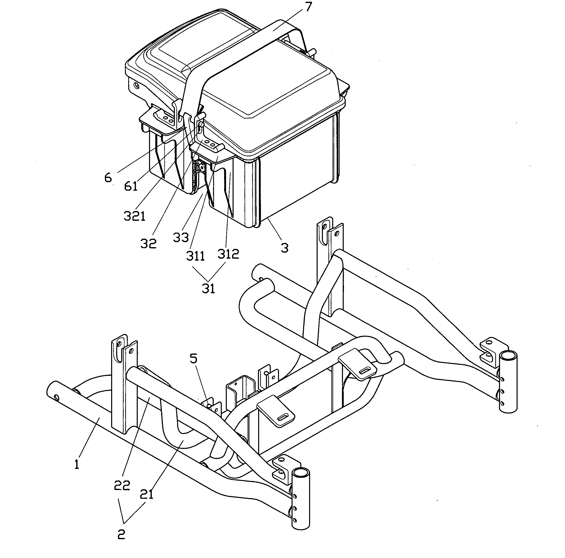
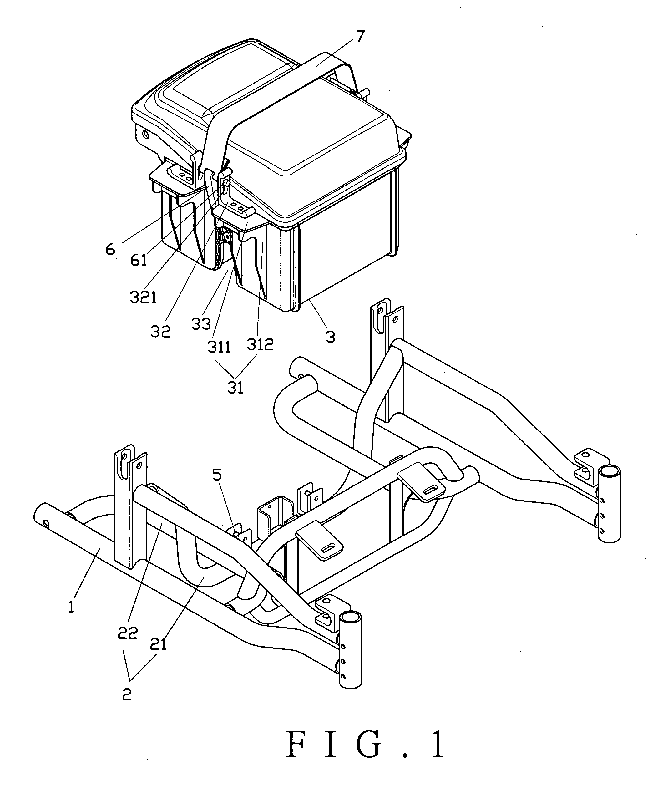
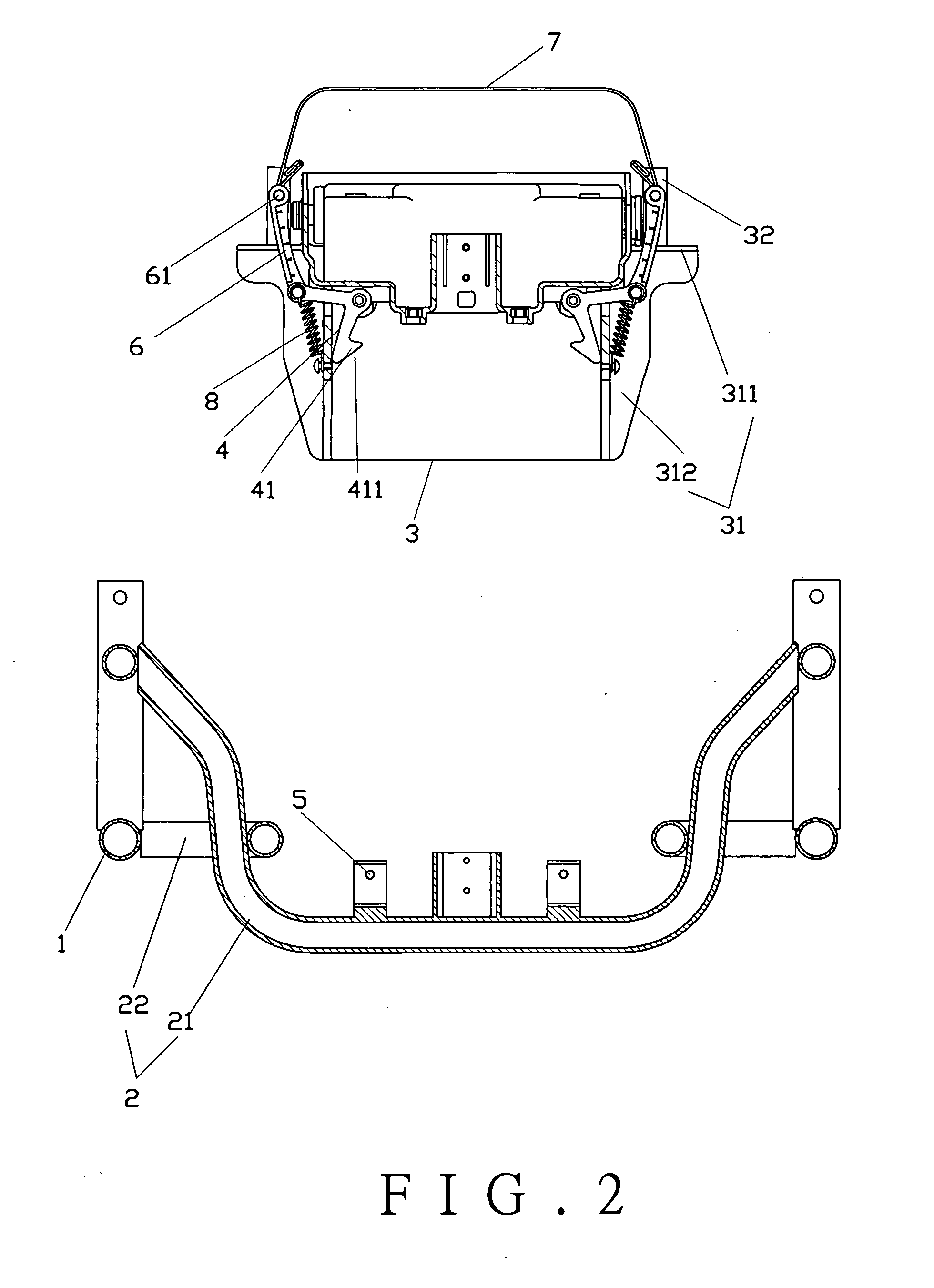
[0019] Referring to FIGS. 1 and 2, a preferred embodiment of the present invention includes a chassis (1), a support unit (2), a battery case (3), hasps (4), retainers (5), connection rods (6), a handle (7), and elastic members (8). The support unit (2) is pivotally connected to the chassis (1). The support unit (2) includes a lever (21) and a pair of bracket rods (22). The bracket rods (22) hold the edge of the battery box (3). Hasp holders (31) are further provided on both sides of the battery case (3) to rest on the bracket rods (22) of the support unit (2). Each hasp holder (31) comprises a flap (311) and upstanding ribbed plates (312). The ribbed plates (312) are located underneath the flap (311) to serve as reinforcement while providing a configuration together with the flap (311) and the edge of the upper section of the ribbed plate (312) to facilitate the placement of the hasp holder (31) in relation to the bracket rod (22). A guide plate (32) is fixed to the hasp holder (31...


PUM


Abstract

A battery quick-release structure for an electric mobility scooter includes a chassis, a battery case, hasps, retainers, connection rods, a handle, and elastic members. The battery case is mounted on the chassis. The retainers are disposed on the chassis. The battery case is provided with the hasps. The hasps are pivotally connected to the connection rods. The connection rods are connected to the handle. Both ends of each elastic member are respectively connected to the hasp and the battery case. The hasps are normally locked to the retainers. The battery case is released for portability by pulling up the handle for the connection rods are to free the hasps from the retainers.

Description

BACKGROUND OF THE INVENTION [0001] (a) Field of the Invention [0002] The present invention relates to a battery quick-release structure for an electric mobility scooter, and more particularly, to one that has a battery case pivoted with hasps to be automatically locked to a chassis and can be easily picked up by pulling up a handle to release the hasps. [0003] (b) Description of the Prior Art [0004] For a battery as a must to electric mobility scooters generally available in the market, it rests on a chassis simply by its weight and is fastened to the chassis with a locking bracket. It prevents easy assembly and disassembly and practically a torture to a driver who is handicapped or senile citizen. [0005] A quick-release mechanism of the prior art also takes advantage of the weight of the battery to snap a battery case into the chassis. However, the battery case is not secured to run the risk of safety concerns as it could easily fall out of the chassis when driving on a bumpy road....

Claims


Application Information

Patent Timeline
Patent Type & Authority Applications(United States)
IPC IPC(8): B60R16/04
CPCB60R16/04Y10S903/907
Inventor TIEN, CHENG-JY
Owner KARMA MEDICAL PRODUCTS CO LTD
Learn More