
Stress and pore pressure limits using a strength of materials approach

Inactive Publication Date: 2007-05-24
GEOMECHANICS INT
View PDF4 Cites 31 Cited by
  • Summary
  • Abstract
  • Description
  • Claims
  • Application Information

AI Technical Summary

Benefits of technology

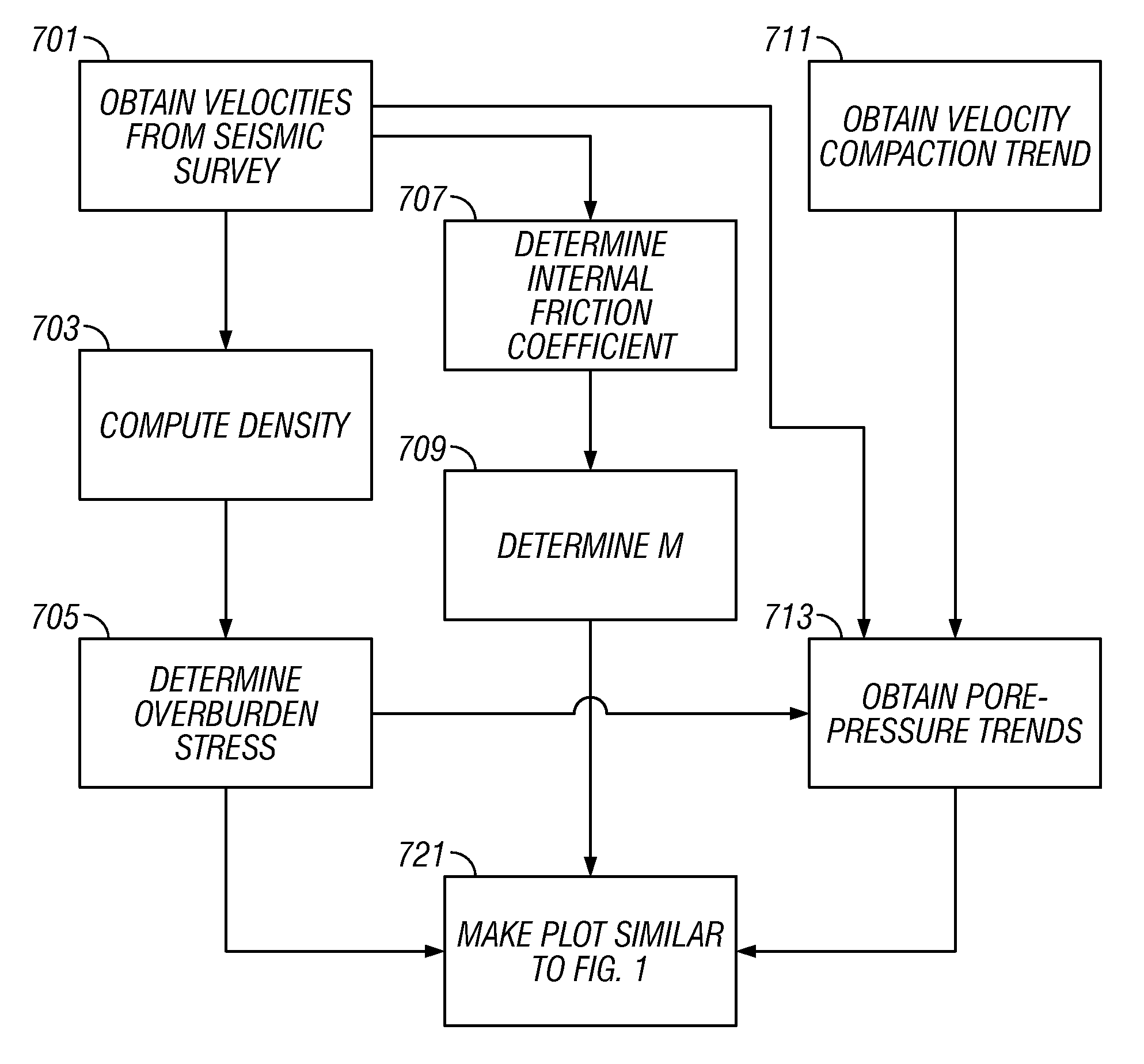
[0010] one embodiment of the measurement is a method of developing a reservoir in and heard formation. Seismic measurements are used for defining the first set of constraints in the stress diagram characterizing the subsurface, this stress diagram being related to principle stresses. Trend data are used for defining additional constraints in the stress diagram. An operation relating to development of the reservoir is performed using the first set of constraints and/or the additional constraints. Using seismic measurements may further involve making seismic measurements. Defining the first set of constraints may be based on using an overburden stress determined from the seismic measurements, a coefficient of friction determined from the seismic measurements, and a pore-pressure trend determined from the overburden stress and a velocity compaction trend. Determining the overburden stress may be based on using

Problems solved by technology

It is almost impossible to measure all of the stresses and the pore pressure at the same depth.
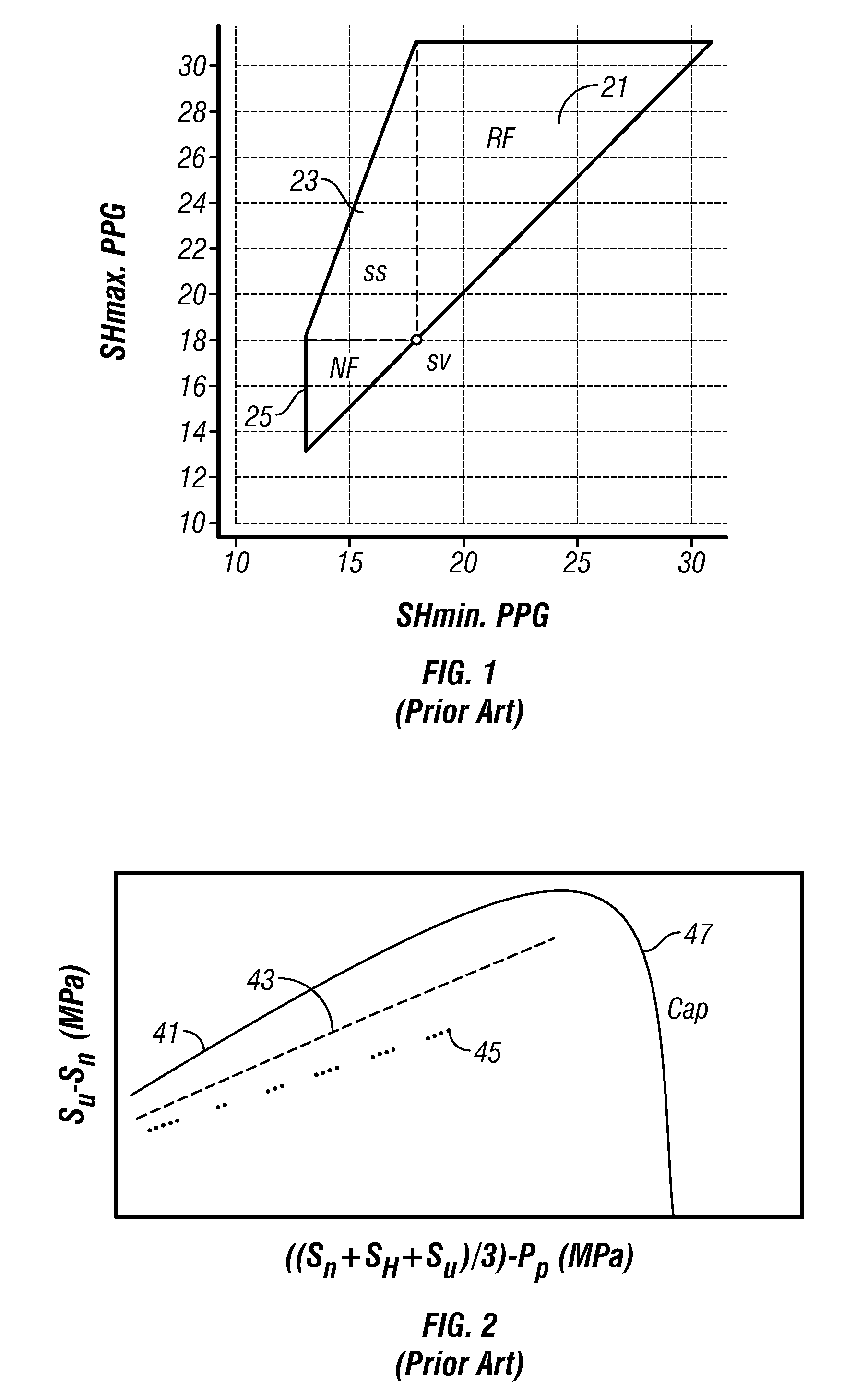
The key to the method revealed by Zoback et al. is that stresses in the crust cannot take on arbitrary values but are limited by the strength of pre-existing fractures and faults.
Because fractures, faults, and microcracks occur in the crust at all scales and all orientations, stresses cannot be such that any of these would fail in shear.
While the constraints given by FIG. 1 are helpful and are used in oilfield development, for most practical purposes they are quite broad and not particularly useful for detailed decision-making on how to develop a reservoir.

Method used


Image

  • Stress and pore pressure limits using a strength of materials approach
  • Stress and pore pressure limits using a strength of materials approach
  • Stress and pore pressure limits using a strength of materials approach

Examples


Embodiment Construction

[0021] The present invention describes a method whereby the strength of the intact rock limits the stress state. In this realization of the invention, the strength model is one that is appropriate for a compacting (young, unlithified) sediment.

[0022] It is known that when small stresses are applied to a rock, the rock initially deforms elastically (that is, upon release of the stress the rock returns to its unstressed state). Past a certain applied (typically, compressive) stress, however, the rock is said to deform plastically and some of the deformation is permanent. Teng-fong Wong and others, as detailed in Schutjens, et al. (2001) described the failure or yield of rocks in compression as having two possible modes. These are strain localization leading to creation of a shear fracture, and distributed, compactive deformation leading to a permanent reduction in volume. Since the volume of the rock is composed of two elements: the solid frame and the (typically, liquid or gas-fille...


PUM


Abstract

A method of developing a reservoir in an earth formation. Seismic measurements are used for defining the first set of constraints in distress diagram characterizing the subsurface. Trend data are used for defining additional constraints in distress diagram. These constraints are used in performing operations for relating to the development of the reservoir.

Description

CROSS-REFERENCES TO RELATED APPLICATIONS [0001] This application claims priority from U.S. Provisional patent application Ser. No. 60 / 738909 filed on 22 Nov. 2005.BACKGROUND OF THE INVENTION [0002] This invention relates generally to evaluation of boreholes. More particularly, this invention relates tools for estimation of stresses in earth formations and the magnitude of pore pressure in the formations. [0003] In order to optimize Oil & Gas operations, it is important to know the earth stresses and the magnitude of the pore pressure. Considerable effort has been devoted to developing methods to determine these parameters using either direct or indirect approaches. Examples of direct approaches include using fluid samplers to measure pore pressure, and using diagnostic miniature fracturing operations (minifracs) or extended leakoff tests to determine the least principal stress (usually, the minimum horizontal stress). Examples of indirect methods include using seismic velocity to es...

Claims


Application Information

Patent Timeline
IPC IPC(8): G01V1/00G06F19/00
CPCG01V1/30G01V2210/6248G01V2210/66
Inventor MOOS, DANIEL
Owner GEOMECHANICS INT
Learn More