Eureka AIR delivers breakthrough ideas for toughest innovation challenges, trusted by R&D personnel around the world.

Exercising apparatus with varying length arms

a technology of varying length arms and exercise equipment, which is applied in the direction of sport apparatus, gymnastic exercise, frictional force resistors, etc., can solve the problems of not all the moving parts of the currently available elliptical trainer not all of the moving parts of the current elliptical trainer are positioned in front of the user, and the linkage is not well coordinated

Inactive Publication Date: 2007-05-24
ICON IP
View PDF7 Cites 104 Cited by
  • Summary
  • Abstract
  • Description
  • Claims
  • Application Information

AI Technical Summary

Benefits of technology

[0011] The apparatus and system of the present invention has been developed in response to the present state of the art, and in particular, in response to the problems and needs in the art that have not been fully solved by currently available exercise equipment. Thus, the present invention provides an exercise apparatus that coordinates the exercise of the lower body with the upper body. Specifically, the exercise apparatus of the present invention better imitates the natural motion of both the upper body and lower body while walking and running.
[0013] The elliptical trainer also includes a drive mechanism known in the art that is mounted to the frame. The drive mechanism provides resistance to the movement of the user and conserves the momentum generated by the movement of the user. The drive mechanism may comprise a belt, a flywheel, a crank, an axle, a frictional element, a motor or any other component known in the art that may be used in a drive mechanism for an exercise machine.
[0014] Two spaced reciprocating members are connected to the drive mechanism so that they move out of phase with each other to actuate the drive mechanism. The reciprocating members include footpads that travel in an elliptical path. Each footpad is shaped to receive and grip a user's shoe or foot to prevent the user from slipping off of the reciprocating member as it moves about an elliptical path. Typically, the footpad is disposed at an angle so that the heel kick that normally accompanies walking or running is accommodated by the foot pad as it travels about the elliptical path.
[0015] Additionally, the reciprocating members include a reciprocating support that helps the reciprocating member convert the circular motion of the drive mechanism into the elliptical motion of the footpad. As the reciprocating member is actuated by a user, the reciprocating support moves back and forth on a track of the frame of the exercise apparatus.
[0016] Because the reciprocating support moves back and forth on a track, a potential pinch point is created. Thus, to help prevent accidents and in accordance with the invention, the reciprocating support is positioned in front of the footpad. By positioning the reciprocating support between the drive mechanism and the footpad, a user can better monitor this pinch point and prevent related accidents from occurring.

Problems solved by technology

However, not all of the moving parts of currently available elliptical trainers are positioned in front of the user.
However, because of the circular motion of the drive mechanism, these devices use complicated linkages to convert the circular motion of the drive mechanism into a back and forth hand motion.
Additionally, these linkages do not coordinate well with the elliptical motion of the footpads.
Furthermore, these linkages may have catch points and may not effectively coordinate the exertion of the upper body with the exertion of the lower body of the user to actuate the drive mechanism.
These linkages may also be unattractive and costly to manufacture and assemble because of the plurality of parts and time required to assemble each part into the linkages.
However, elliptical hand motion may feel uncomfortable and unnatural to many users.
Additionally, users tend to move their feet further than their hands so that the elliptical hand motion is too long and thus, may cause muscle strain.

Method used


Image

  • Exercising apparatus with varying length arms
  • Exercising apparatus with varying length arms
  • Exercising apparatus with varying length arms

Examples


Embodiment Construction

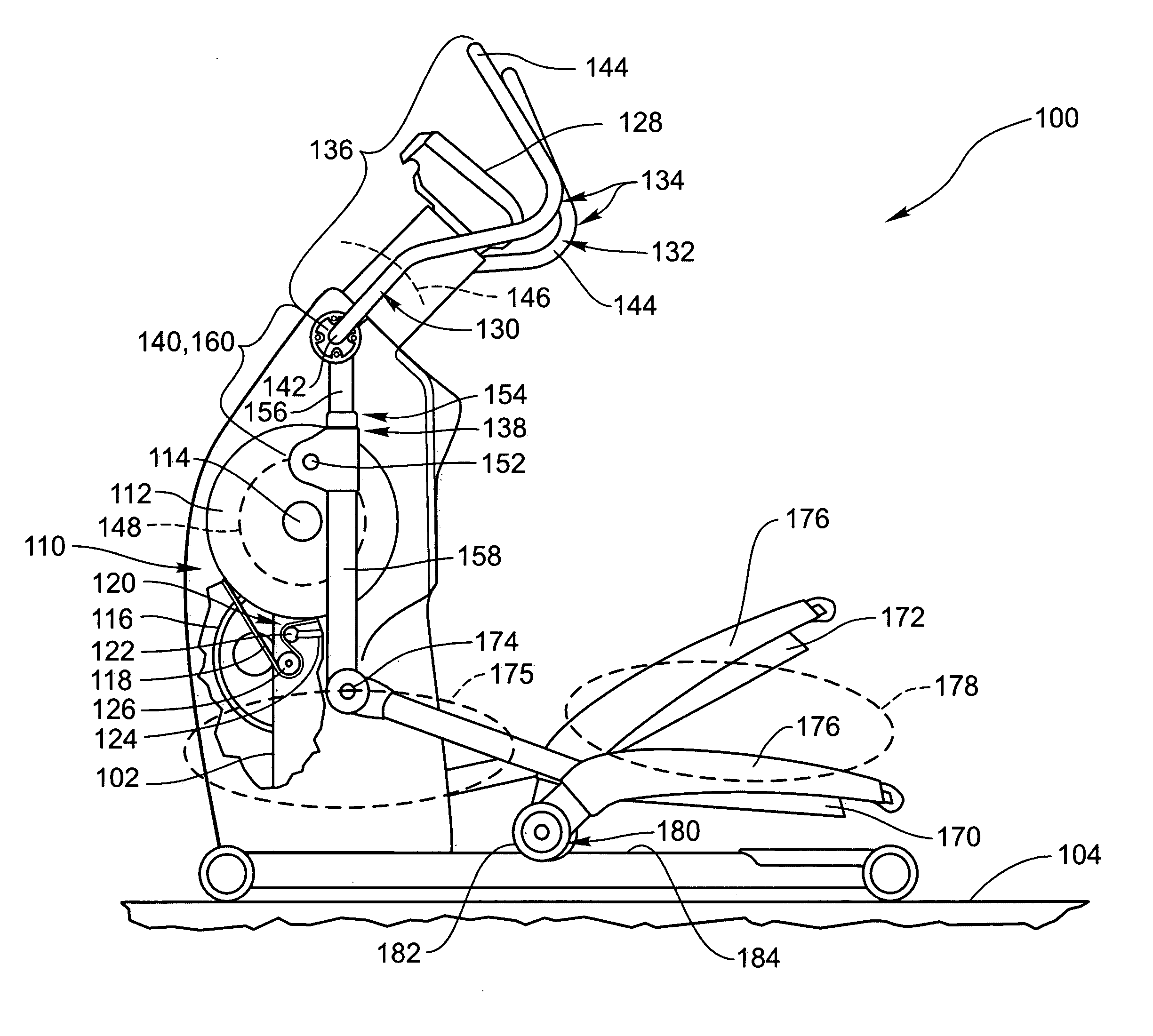
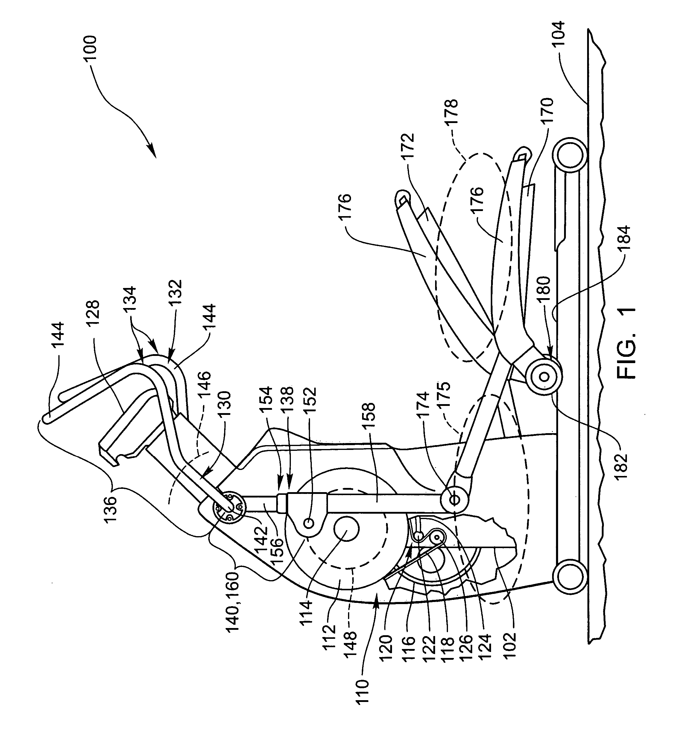
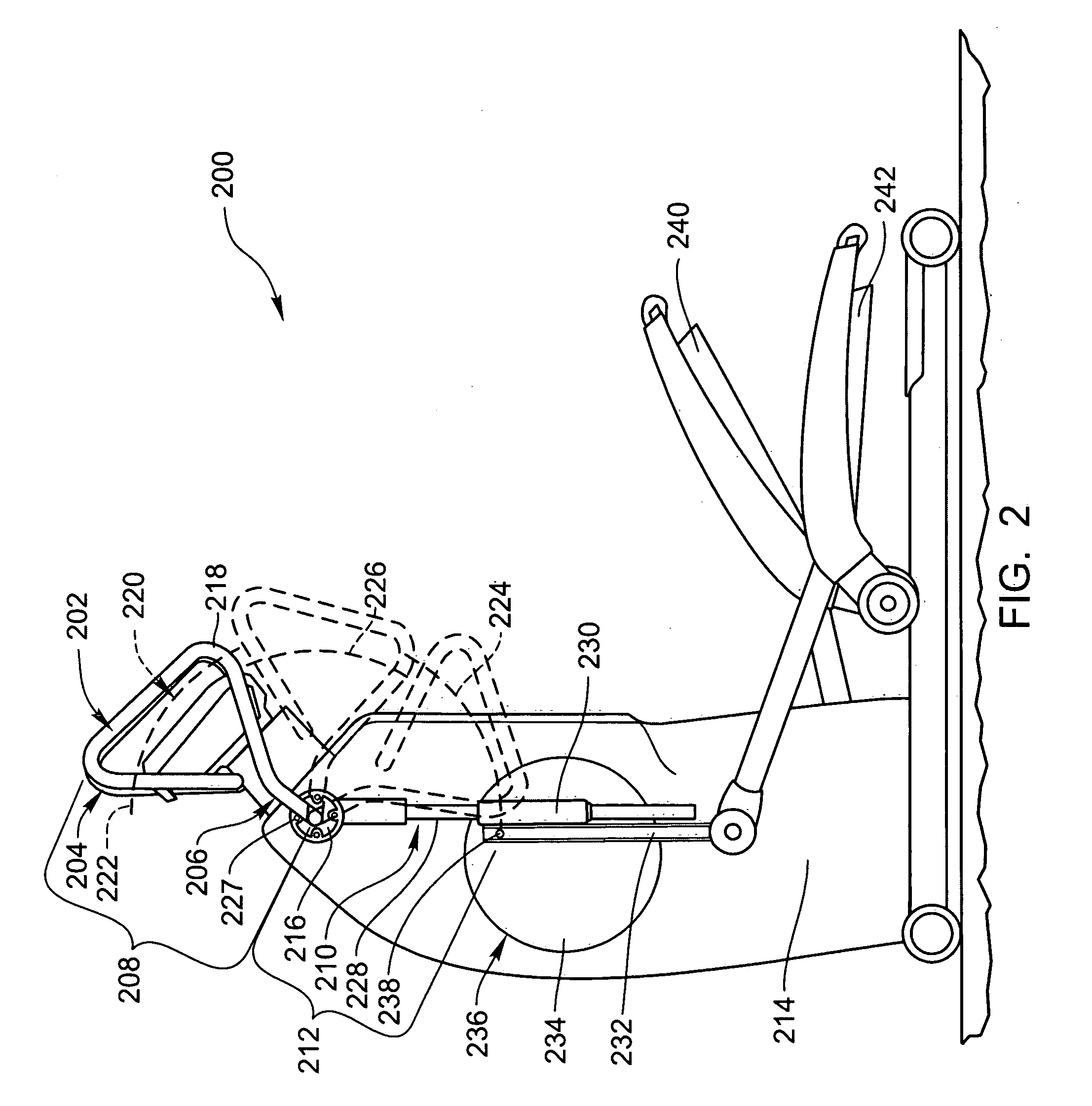
[0029] The presently preferred embodiments of the invention will be best understood by reference to the drawings, wherein like parts are designated by like numerals throughout. It will be readily understood that the components of the present invention, as generally described and illustrated in the figures herein, could be arranged and designed in a wide variety of different configurations. Thus, the following more detailed description of the embodiments of the exercise apparatus of the present invention, as represented in FIGS. 1 through 6, is not intended to limit the scope of the invention, as claimed, but is merely representative of presently preferred embodiments of the invention.

[0030] Referring to FIG. 1, a partially cut away side view illustrates an exercise apparatus 100 of the invention. As shown, the exercise apparatus 100 is an upright elliptical trainer that includes a frame 102 shaped to be stably supported by a floor 104.

[0031] A drive mechanism 110 is mounted to the...


PUM


Abstract

An exercise apparatus, such as a front end or an upright elliptical trainer, includes a drive mechanism connected to a first reciprocating member and a second reciprocating member. Each reciprocating member includes a footpad that travels in an elliptical path. The exercise apparatus also includes a first arm member and a second arm member connected to the drive mechanism. Each arm member includes a first portion having a handle that travels in a back and forth path and a second portion having at least a part of which that travels in a circular or elliptical path. To convert the circular motion of the second portion to the back and forth motion of the handle, the second portion has an effective variable length that permits the distance between a first connection point and a second connection point of the arm members to change as the drive mechanism is actuated.

Description

BACKGROUND OF THE INVENTION [0001] The present invention relates generally to stationary exercise equipment. More specifically, the present invention relates to front end and upright elliptical trainers that coordinate the elliptical foot motion normally associated with walking and running with a back and forth hand motion. In other words, the present invention permits a user to exercise both their upper body and lower body in a coordinated fashion. Of course, this invention may be applied to other types of exercise equipment. [0002] Generally, elliptical trainers are exercise machines where a user's feet travel in diametrically opposed elliptical paths that roughly simulates the natural path the user's feet would follow while running or walking. Elliptical trainers provide the advantage of permitting a user to exercise their lower body without the jarring effects normally associated with running and walking. [0003] Typically, elliptical trainers provide resistance to the motion of ...

Claims


Application Information

Patent Timeline
Patent Type & Authority Applications(United States)
IPC IPC(8): A63B22/04
CPCA63B21/005A63B21/012A63B21/225A63B22/001A63B22/0015A63B22/0664A63B2022/0005A63B2022/0676A63B2210/50A63B22/0005
Inventor ERCANBRACK, GAYLEN W.DALEBOUT, WILLIAM T.HOWELL, HENRY J.ALLEMAN, ROBERT L.
Owner ICON IP
Why Eureka
Eureka Blog
Learn More