Resilient plug and a watertight connector

a plug and connector technology, applied in the direction of coupling base/case, coupling device connection, securing/insulating coupling contact member, etc., can solve the problem of reducing operation efficiency

Inactive Publication Date: 2007-05-24
SUMITOMO WIRING SYST LTD
View PDF5 Cites 10 Cited by
  • Summary
  • Abstract
  • Description
  • Claims
  • Application Information

AI Technical Summary

Benefits of technology

[0011] The entanglement preventing portion preferably projects at least partly from the rear end of the cavity. Thus, even if the wire is shaken, the influence of deformation does not go beyond the entanglement preventing portion and the lips are not deformed. Therefore, the lips can be held in close contact with the inner wall of the cavity and the wire, enabling a watertight function to be maintained.

Problems solved by technology

This entanglement of the wires W3, W4 creates problems and reduces operational efficiency.

Method used


Image

  • Resilient plug and a watertight connector
  • Resilient plug and a watertight connector
  • Resilient plug and a watertight connector

Examples


Embodiment Construction

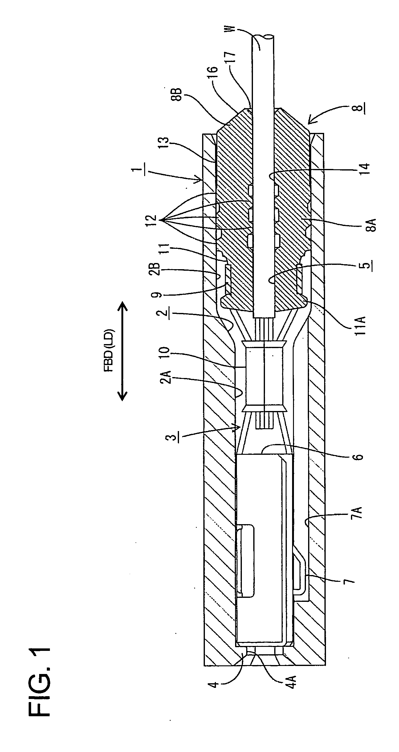
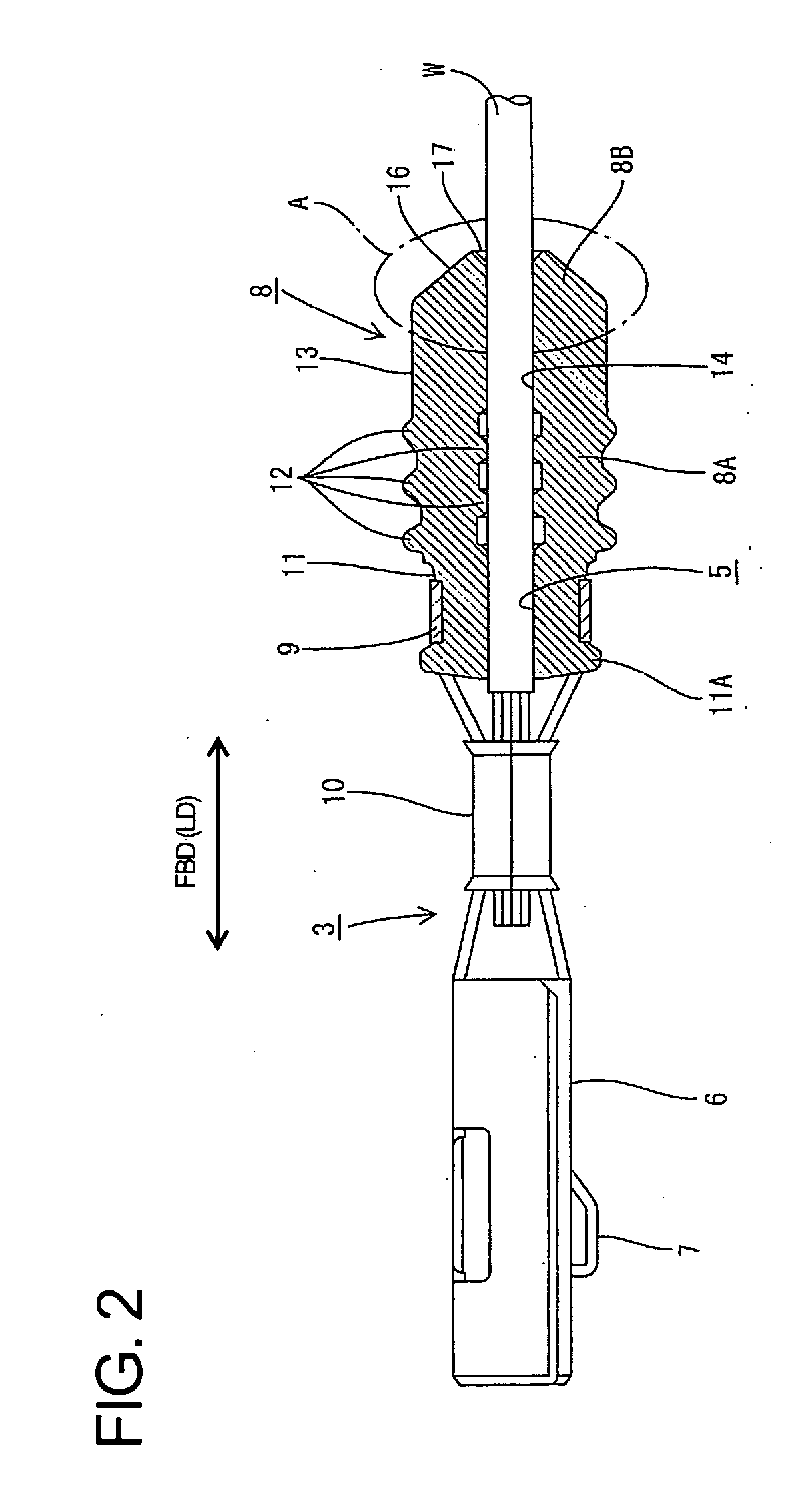
[0019] A watertight connector according to a first embodiment of the invention is described with reference to FIGS. 1 to 4. The connector has a housing 1 and at least one cavity 2 penetrates the housing 1 in forward and backward directions FBD. A terminal accommodating hole 2A is defined at a front part of the cavity 2 and a substantially cylindrical plug-mounting hole 2B is defined at a rear part of the cavity 2. A terminal fitting 3 can be inserted into the cavity 2 from behind, as shown in FIG. 1. The terminal fitting 3 is stopped at a frontmost position by a front wall 4 of the cavity 2, and is prevented from coming out backward by a lock (not shown) in the cavity 2. A substantially rectangular tube 6 is formed at the front of the terminal fitting 3 and is accommodated in the terminal accommodating hole 2A. A plug 8, of rubber or other resilient material, is mounted on a rear part of the terminal fitting 3 and is accommodated in the plug mounting hole 2B. The front wall 4 is for...


PUM


Abstract

A rubber plug (8) has a tubular main portion (8A) and a wire inserting hole (5) penetrates the main portion (8A) along a central axis (C) for receiving a wire (W). The main portion (8A) includes an inner lip portion (13) and an outer lip portion (14) having lips (12) circumferentially formed on the inner and outer circumferential surfaces of the main portion (8A). A tapered entanglement preventing portion (8B) extends from an opening edge (17) of the wire insertion hole (5) to a rear peripheral edge (13A) of the outer lip portion (13). Another wire (W) slides on the tapered surface (16) to avoid entanglement.

Description

BACKGROUND OF THE INVENTION [0001] 1. Field of the Invention [0002] The invention relates to a resilient plug and to a watertight connector. [0003] 2. Description of the Related Art [0004] Japanese Unexamined Patent Publication No. 2002-280108 discloses a rubber plug that can be mounted over a wire. A terminal fitting then is crimped into engagement with the wire and the rubber plug. The assembly of the terminal fitting, the rubber plug and the wire then is inserted into a cavity of a connector housing. As a result, the rubber plug is squeezed between an inner peripheral surface of the cavity and an outer peripheral surface of the wire to prevent water from entering into the cavity. Assemblies of the terminal fittings, the rubber plugs and the wires are bundled together prior to insertion into the cavities, as shown in FIG. 6. However, a wire W4 that is pulled from the bundle of wires shown in FIG. 6 is likely to get caught by a wire W3 connected with another terminal fitting becaus...

Claims


Application Information

Patent Timeline
Patent Type & Authority Applications(United States)
IPC IPC(8): H01R13/52
CPCH01R13/5205
Inventor TANAKA, TSUTOMU
Owner SUMITOMO WIRING SYST LTD
Why Eureka
Try Eureka