
Display device having an adjustable counterweight structure

Inactive Publication Date: 2007-05-24
HANNSPREE INC
View PDF7 Cites 2 Cited by
  • Summary
  • Abstract
  • Description
  • Claims
  • Application Information

AI Technical Summary

Benefits of technology

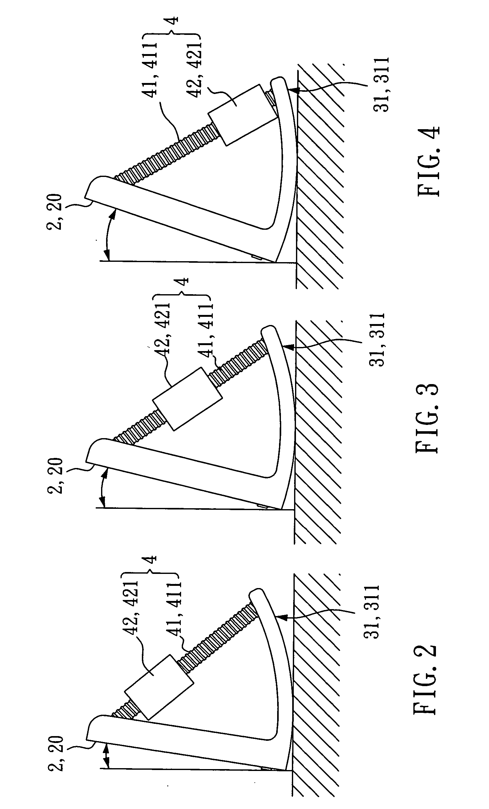
[0008] The present invention provides a display device having an adjustable counterweight structure. According to the first embodiment, the display device comprises a display, a base, and an adjustable counterweight structure. The base is fixedly provided at the bottom side of the display, and has a convex bottom surface. The adjustable counterweight structure comprises a connecting member linking the display and the base, and a weight mounted on and movable along the connecting member. The user can move the weight along the connecting member with single hand to adjust the center of gravity of the display device and to further adjust the viewing angle of the display subject to the curvature of the convex bottom surface of the base. Further, because of the effect of the convex bottom surface of the base, the whole structure of the display device has the function of self-balance that neutralizes oscillation or vibration caused by an external force or effect of the environment, preventing falling of the display or any unnecessary loss due to damage of the display device. Further, the whole assembly of the display device has a simple structure that is convenient and inexpensive to manufacture and easy to manufacture. Further, the avant-garde but simple design provides a totally new outer appearance that attracts consumers' attention, encouraging them to buy the product.
[0013] The aforesaid second embodiment allows the user to adjust the position of the weight with single hand so as to further change the center of gravity of the display device and the viewing angle of the display, i.e., the second embodiment achieves the same effects as the aforesaid first embodiment.
[0017] The aforesaid third embodiment allows the user to adjust the position of the weight with single hand so as to further change the center of gravity of the display device, thereby adjusting the viewing angle of the display.

Problems solved by technology

A conventional CRT monitor is large and heavy, and tends to produce radiation that is harmful to the human body.
However, conventional pivot joints and hinge mechanisms for LCDs commonly have a complex structure that is expensive and not easy to be manufactured.
Most LCDs have slim body designs therefore tend to fall upon oscillation or vibration.
Further, when adjusting the viewing angle, the user must hold the base with one hand and tilt the screen with the other hand thus this adjustment procedure is inconvenient.
Further, LCDs using these conventional pivot joints or hinge mechanisms commonly have a monotonous outer appearance that give no desirable impression to consumers and cannot adequately cause consumers to buy them.

Method used


Image

  • Display device having an adjustable counterweight structure
  • Display device having an adjustable counterweight structure
  • Display device having an adjustable counterweight structure

Examples


first embodiment

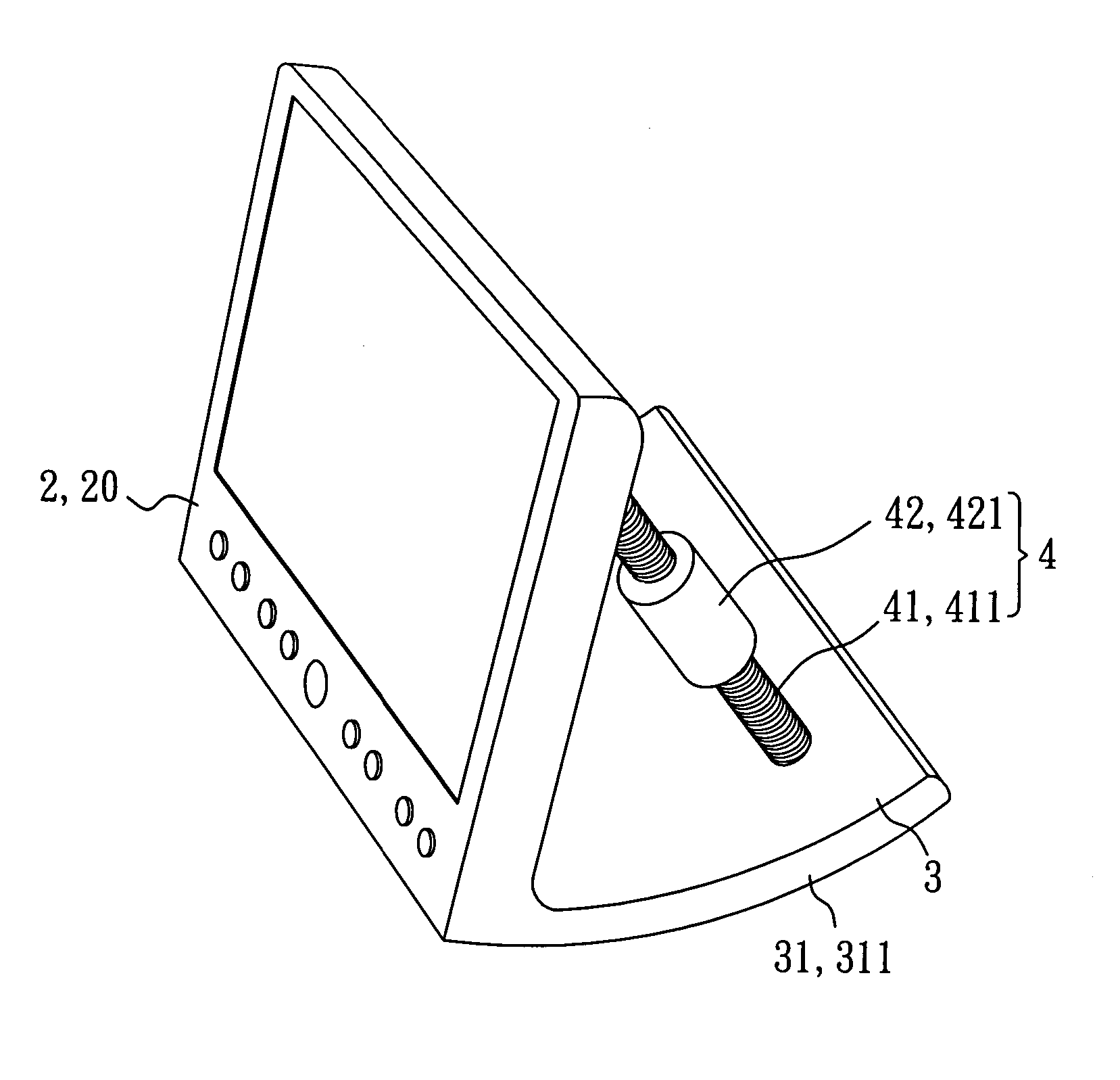
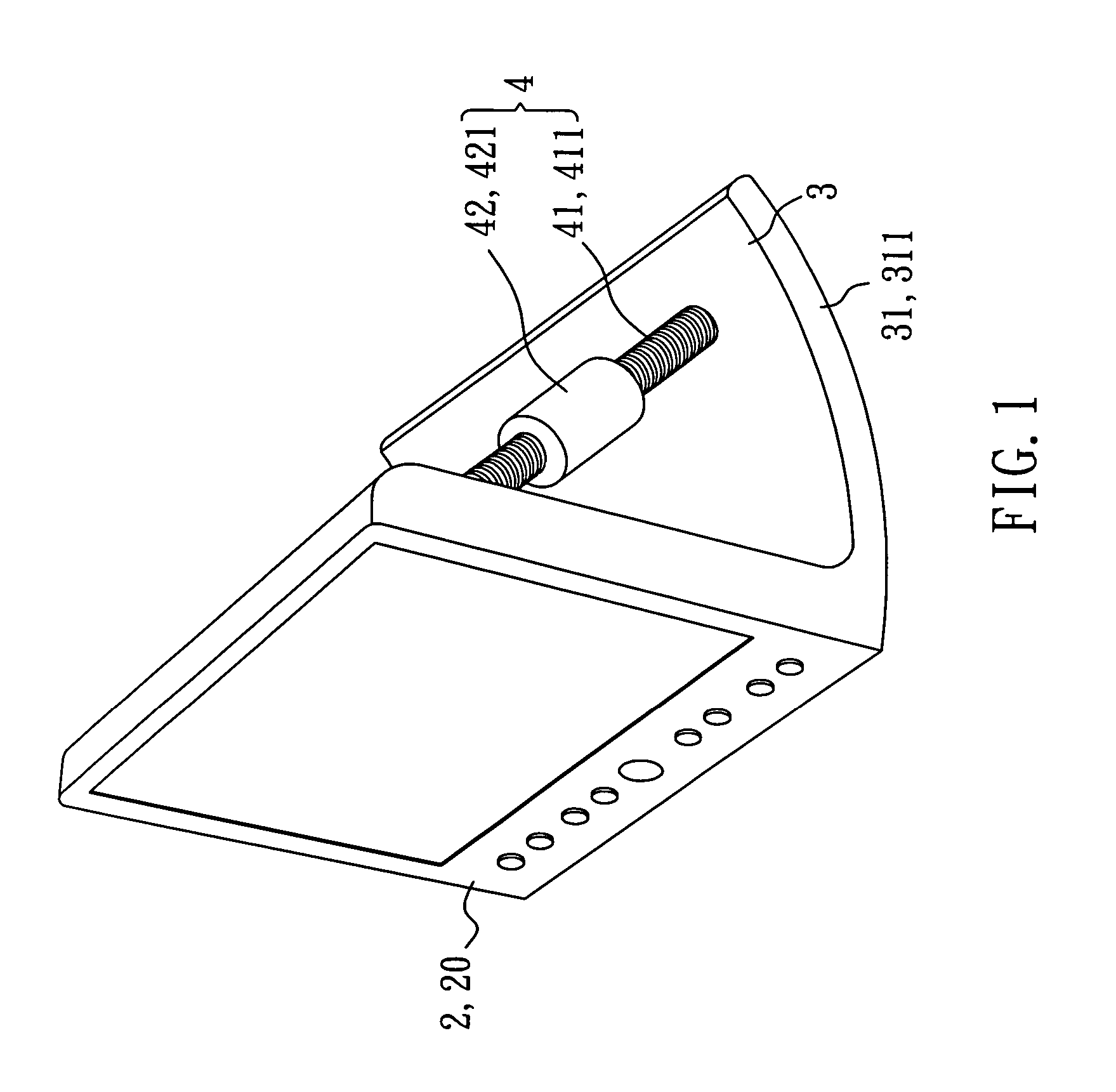
[0031] Referring to FIGS. 1˜4, a display device in accordance with the present invention is shown comprised of a display 2, a base 3, and an adjustable counterweight structure 4. The display 2 is fixedly connected to one end of the base 3. The base 3 has a convex bottom surface 31. Further, the adjustable counterweight structure 4 comprises a connecting member 41 and a weight 42. The connecting member 41 is connected between the display 2 and the base 3. The weight 42 is movable along the connecting member 41.

[0032] As shown in FIG. 1, the display 2 is a flat-panel display 20. The convex bottom surface 31 of the base 3 is a circular arcuate surface 311. Alternatively, the convex bottom surface 31 can be an elliptical arcuate surface, a parabolically curved surface, a double curved surface, or even a spherical surface, an ellipsoid or a paraboloid, subject to the desired design. According to this embodiment, the connecting member 41 is a screw rod 411, and the weight 42 is a nut 421 ...

sixth embodiment

[0039]FIG. 9 shows a display device constructed according to the present invention. According to this embodiment, the display device comprises a display 51, a base 6, and an adjustable counterweight structure 7. The display 51 is fixedly connected to one end of the base 6. The base 6 has a convex bottom surface 61. The adjustable counterweight structure 7 comprises a guide 71 and a weight 72. The guide 71 is provided at the base 6. The weight 72 can be moved along the guide 71 toward or away from the display 51 and then firmly positioned on the guide 71 at the desired location by means of a tightening up force or friction force.

[0040] As illustrated in FIG. 9, the display 51 according to this embodiment is a flat-panel display 511, and the convex bottom surface 61 of the base 6 is a circular arcuate surface 611. Alternatively, the convex bottom surface 61 can be an elliptical arcuate surface, a parabolically curved surface, a double curved surface, or even a spherical surface, an el...

eighth embodiment

[0044]FIG. 11 shows a display device constructed according to the present invention. According to this embodiment, the display device comprises a display 81, a base 82, an adjustable counterweight structure 9, and a positioning structure 93. The display 81 is fixedly connected to one end of the base 82. The base 82 has a convex bottom surface 821. Further, the adjustable counterweight structure 9 comprises a guide 91 and a weight 92. The guide 91 is provided at the backside of the display 81 and has a C-shaped cross section. The weight 92 is movable along the guide 91 up or down relative to the base 82. Further, the positioning structure 93 is adapted to locate the weight 92 on the guide 91 at a particular location.

[0045] As shown in FIG. 11, the display 81 is a flat panel display 811. The convex bottom surface 821 of the base 82 is a circular arcuate surface 822. Alternatively, the convex bottom surface 821 can be an elliptical arcuate surface, a parabolically curved surface, a dou...


PUM


Abstract

A simple structure of display device having the function of self-balance and prevent falling caused by an external force is disclosed to include a display, a base, which has a convex bottom surface and is fixedly connected to the bottom side of the display, and an adjustable counterweight structure, which has a weight that can be moved with one hand to change the center of gravity of the display device and to further adjust the viewing angle of the display.

Description

BACKGROUND OF THE INVENTION [0001] 1. Field of the Invention [0002] The present invention relates to display devices and more particularly, to a flat-panel display having an adjustable counterweight structure. [0003] 2. Description of Related Art [0004] A conventional CRT monitor is large and heavy, and tends to produce radiation that is harmful to the human body. Due to the aforesaid drawbacks, flat-panel displays such as LCD (Liquid Crystal Display) have been intensively used to replace conventional CRT monitors. Following rapid development of LCD technology and cost reduction through mass production, flat-panel displays have become extremely popular and have become the dominant display device on the market. [0005] An LCD has a liquid crystal cell positioned between two polarizers. An electric field is applied to the liquid crystal cell to make light pass through cell. The liquid crystal filled in the cell, therefore, is like a shutter, either allowing light to pass through or blo...

Claims


Application Information

Patent Timeline
IPC IPC(8): A47G1/16
CPCF16M11/10F16M2200/041G06F1/1601G06F2200/1612Y10S248/923
Inventor LIOU, GUAN-DEHUANG, CHIA-PINELAI, LI-LITSAI, STEPHEN
Owner HANNSPREE INC
Learn More