Multi-tiered virtual local area network (VLAN) domain mapping mechanism

a virtual local area network and domain mapping technology, applied in the field of computer networks, can solve the problems of difficult to ascertain from which particular network traffic originated, requires man to include expensive networking equipment, and can be expensive to build and opera

Inactive Publication Date: 2007-05-17
CISCO TECH INC
View PDF20 Cites 41 Cited by
  • Summary
  • Abstract
  • Description
  • Claims
  • Application Information

AI Technical Summary

Benefits of technology

[0025] The bridge may also include or have access to certain resources or services, such as priority queues, filter settings, queue selection strategies, congestion control algorithms, high-speed links, etc., for use in forwarding network messages. A particular resource(s) may be selected for use in forwarding the frame based on the frame's provider CoS value.

Problems solved by technology

The need to convert each network message from Ethernet to ATM and back again requires the MAN to include expensive networking equipment.
As a result, MANs can be expensive to build and operate.
Once such traffic enters the MAN, it can be difficult to ascertain from which particular network the traffic originated.
This could result in forwarding errors by the MAN.

Method used


Image

  • Multi-tiered virtual local area network (VLAN) domain mapping mechanism
  • Multi-tiered virtual local area network (VLAN) domain mapping mechanism
  • Multi-tiered virtual local area network (VLAN) domain mapping mechanism

Examples


Embodiment Construction

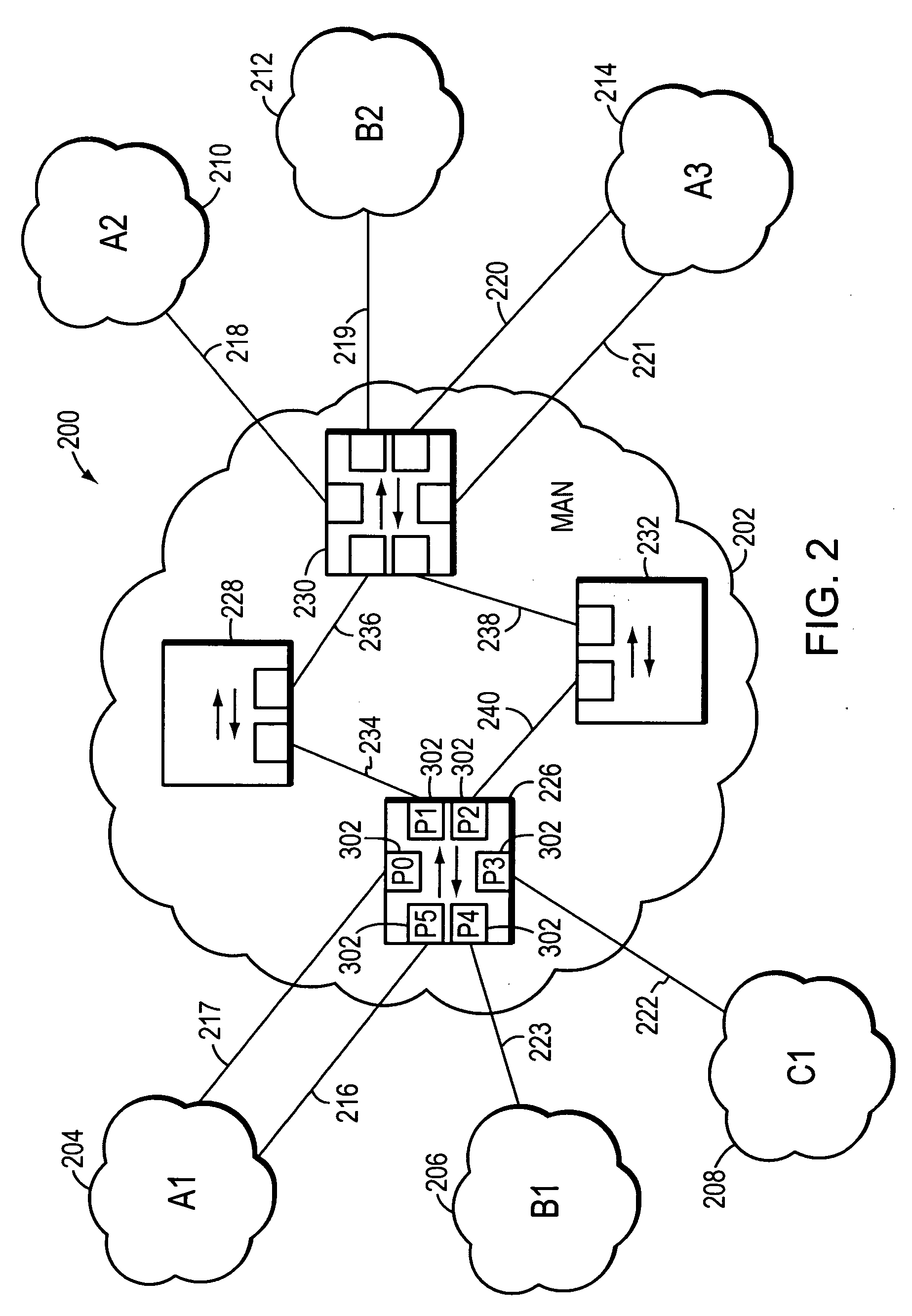
[0032]FIG. 2 is a highly schematic illustration of a computer network 200. Computer network 200 includes a Metropolitan Area Network (MAN) 202 and a plurality of customer networks, such as customer networks 204-214. The MAN 202, which is also referred to as the provider network provides, among other things, interconnection services to the customer networks 204-214. In the illustrative embodiment, each customer network 204-214 comprises a plurality of entities or hosts, such as personal computers, workstations, servers, etc., which are all in the same general location, and are interconnected to form one or more Local Area Networks (LANs) so that the entities may source or sink data frames to one another. As used herein, the term “same general location” refers to a single building or a plurality of buildings on a single campus or within the area of roughly a single city block. The LANs of the customer networks 204-214 may be interconnected by one or more customer operated intermediate...


PUM


Abstract

In one embodiment, a first port of a device provides connectivity to a customer network and a second port of the device provides connectivity to a provider network. Frame mapping logic associated with the first port processes a network message received at the first port and accesses a Virtual Local Area Network (VLAN) mapping data structure that maps customer VLAN designations used in the customer network to provider VLAN designations used in the provider network. Frame mapping logic uses the VLAN mapping data structure to associate the received network message with a particular provider VLAN designation based upon the received network message's particular customer VLAN designation. The received network message is then passed toward the second port.

Description

CROSS-REFERENCE TO RELATED APPLICATION [0001] The present application is a continuation of U.S. patent application Ser. No. 10 / 282,846, which was filed on Oct. 29, 2002, by Suran S. De Silva and Norman W. Finn for a MULTI-TIERED VIRTUAL LOCAL AREA NETWORK (VLAN) DOMAIN MAPPING MECHANISM.BACKGROUND OF THE INVENTION [0002] 1. Field of the Invention [0003] The present invention relates to computer networks and, more specifically, to computer networks that have been segmented into a plurality of Virtual Local Area Net-works (VLANs). [0004] 2. Background Information [0005] A computer network typically comprises a plurality of interconnected entities. An entity may consist of any network device, such as a server or end station, that “sources” (i.e., transmits) or “sinks” (i.e., receives) data frames. A common type of computer network is a local area network (“LAN”) which typically refers to a privately owned network within a single building or campus. LANs typically employ a data communic...

Claims


Application Information

Patent Timeline
Patent Type & Authority Applications(United States)
IPC IPC(8): H04L12/28H04L12/46H04L12/56
CPCH04L12/4641H04L47/2491H04L49/205H04L49/3018H04L49/351H04L49/354H04L2012/5665
Inventor DE SILVA, SURAN S.FINN, NORMAN W.
Owner CISCO TECH INC
Why Eureka
Try Eureka