Image Reader

a technology of image reader and reader, which is applied in the field of image reader, can solve the problems of disassembly of image reader and the inability of the user of image reader to adjust the distance between the platen glass and the cis

Active Publication Date: 2007-05-17
BROTHER KOGYO KK
View PDF7 Cites 13 Cited by
  • Summary
  • Abstract
  • Description
  • Claims
  • Application Information

AI Technical Summary

Benefits of technology

[0011] Aspects of the invention provide an image reader that can adjust a distance between a platen glass and a close-contact-type image sensor without disassembly.
[0014] Further, by allowing the support member moving unit to move the sensor support member to the moving blocking position, the spacer is brought into contact with the spacer contact member. Due to this contacting of the spacer, the spacer is made to slide. In response to such sliding of the spacer, the distance adjusting unit changes a distance between the platen glass and the close-contact-type image sensor (hereinafter also referred to as a glass-CIS distance). That is, by bringing the spacer into contact with the spacer contact member thus making the slider slide, it is possible to adjust a focusing center position of the close-contact-type image sensor. Here, the focusing center position implies a position at which the close-contact-type image sensor is focused. Further, it is unnecessary to perform the manual operation to adjust the glass-CIS distance and hence, it is possible to adjust the distance between the platen glass and the close-contact-type image sensor without disassembling the image reader.
[0015] Still further, by preliminarily setting a sliding quantity of the spacer, it is possible to finely adjust the glass-CIS distance.

Problems solved by technology

However, there has been a drawback that when it is necessary to readjust the distance between the platen glass and the CIS with respect to the once-assembled image reader at the time of shipment from a factory, there has been a drawback that it is necessary to disassemble the image reader so as to manually handle the spacers and the height adjustment screws which are mounted in the inside of the image reader.
Further, since it is necessary to disassemble the image reader to adjust the distance between the platen glass and the CIS as described above, a user of the image reader cannot adjust the distance between the platen glass and the CIS after purchasing the image reader.

Method used


Image

  • Image Reader
  • Image Reader
  • Image Reader

Examples


Embodiment Construction

[0027] Embodiments of the present invention will be described in conjunction with drawings hereinafter.

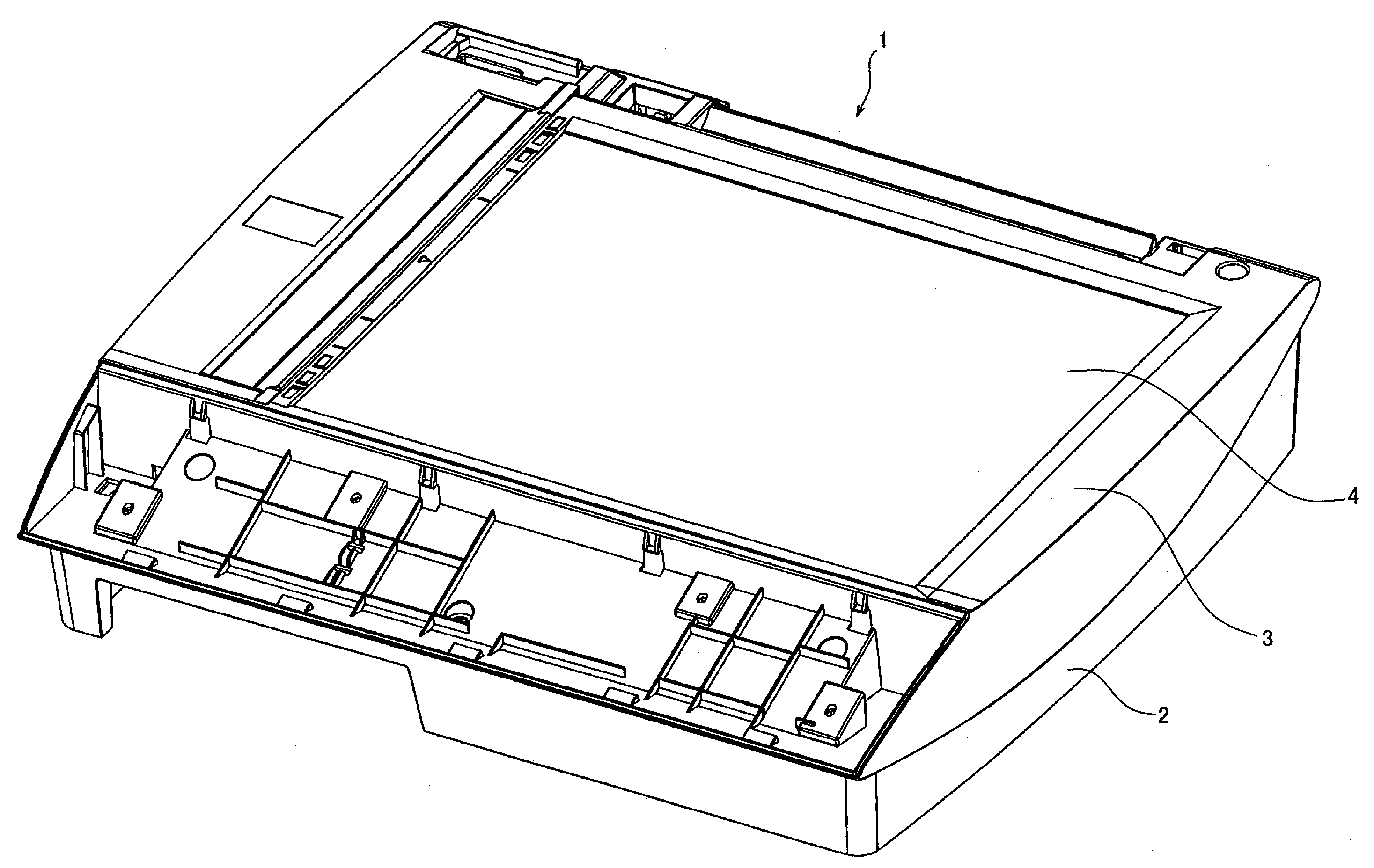
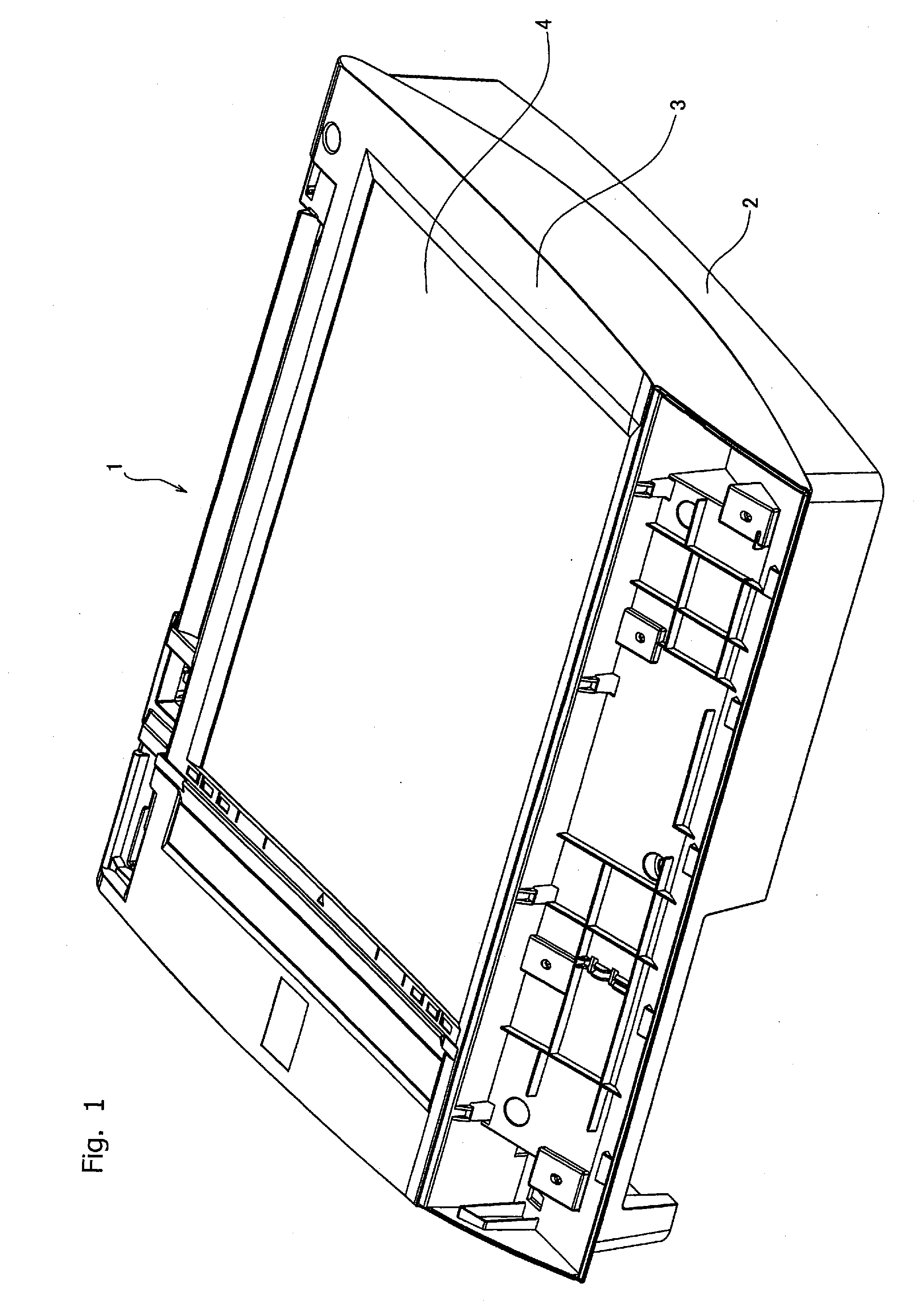
[0028] As shown in FIG. 1, a scanner device 1 is of a flat bed type. The scanner device 1 includes a housing 2 which is formed in a box shape with an upper surface thereof opened and houses constitutional elements of the scanner device 1 in the inside thereof, a rectangular shaped platen glass 4 which is arranged at the center of an upper-surface opening portion of the housing 2 and on which a document is placed, and an upper-surface cover 3 which is arranged on a peripheral portion of the upper-surface opening portion of the housing 2 and supports the platen glass 4.

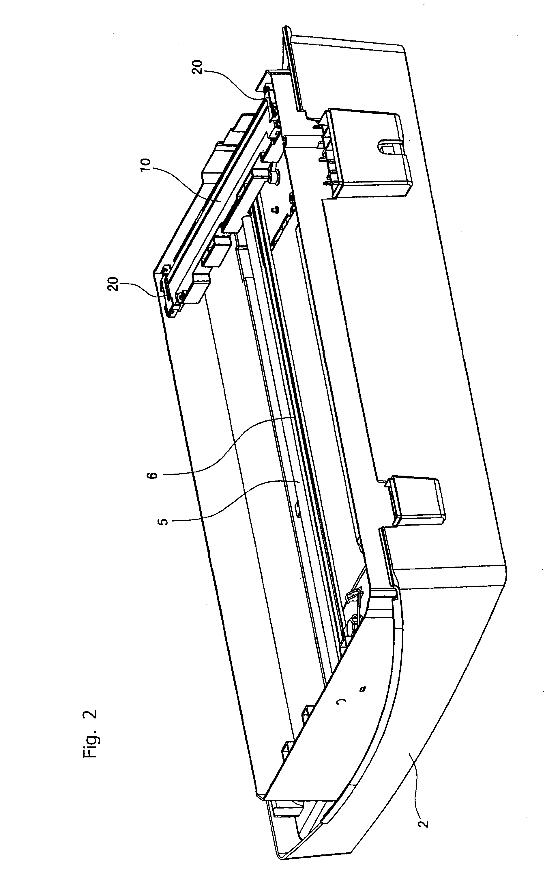
[0029] Further, as shown in FIG. 2, in the housing 2, a close-contact-type image sensor unit (hereinafter referred to as CIS unit) 10, a guide shaft 5, and an endless belt 6 are housed. The CIS unit 10 has a close-contact-type image sensor 12 (see FIG. 3A and FIG. 3B, hereinafter referred to as the CIS) in which a pl...


PUM


Abstract

In an image reader that can adjust a distance between a platen glass and a close-contact-type image sensor (CIS) without disassembly, a CIS unit includes a CIS and a resilient body which biases the CIS toward the platen glass. A CIS roller holder includes a spacer, and a CIS holder which holds the spacer movably in the vertical direction as well as in the sub scanning direction with respect to the platen glass and is fixed to the CIS unit. Irregularities are formed on surfaces of the CIS holder and the spacer which face each other and are engageable by fitting. When the CIS unit is moved in the sub scanning direction and the CIS roller holder is brought into contact with one rib ,the CIS roller holder is brought into contact with the spacer at projections or recesses, thus changing a distance between the platen glass and the CIS.

Description

CROSS-REFERENCE TO RELATED APPLICATIONS [0001] This application claims priority from Japanese Patent Application No. P2005-286464, filed on Sep. 30, 2005, the entire subject matter of which is incorporated herein by reference. BACKGROUND OF THE INVENTION [0002] 1. Field of the Invention [0003] Illustrative aspects of the present invention relate to an image reader that reads an image using a close-contact-type image sensor. [0004] 2. Description of the Related Art [0005] Conventionally, as an image reader, which is mounted on a facsimile, a copying machine or the like, an image reader which uses a close-contact-type image sensor (CIS: Contact Image Sensor) is known. [0006] The CIS is advantageous compared with an image sensor of a charge Coupled Devices (CCD) method with respect to a point that the CIS can be largely miniaturized and can largely reduce a weight thereof. On the other hand, compared with the image sensor of the CCD method, the CIS has a drawback that a focusing depth ...

Claims


Application Information

Patent Timeline
Patent Type & Authority Applications(United States)
IPC IPC(8): H04N1/04
CPCH04N1/1013H04N2201/02404H04N2201/02414H04N2201/02425H04N2201/02427H04N2201/02447H04N2201/0456
Inventor SAKAKIBARA, AKIHIRO
Owner BROTHER KOGYO KK
Why Eureka
Try Eureka