
Method and apparatus for holographic refractometry

Inactive Publication Date: 2007-05-17
PHASE HOLOGRAPHIC IMAGING PHI
View PDF4 Cites 19 Cited by
  • Summary
  • Abstract
  • Description
  • Claims
  • Application Information

AI Technical Summary

Benefits of technology

[0007] Accordingly, it is an objective of the invention to provide a method and a device that makes it possible to automate the process of measuring the refractive index of an object.

Problems solved by technology

Thus, the method does not lend itself for automation.
Thus, it is not possible to make an image of the object and to analyze the image afterwards in another environment or at another time.

Method used


Image

  • Method and apparatus for holographic refractometry
  • Method and apparatus for holographic refractometry
  • Method and apparatus for holographic refractometry

Examples


Embodiment Construction

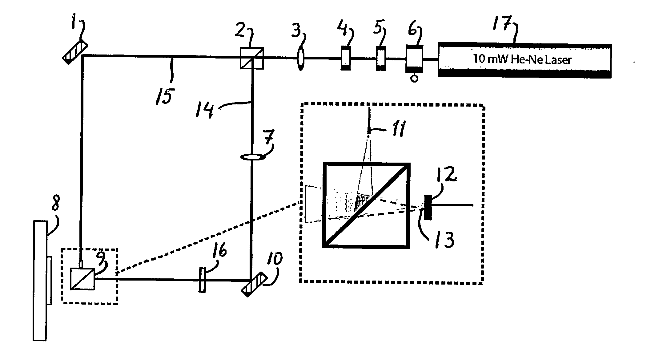
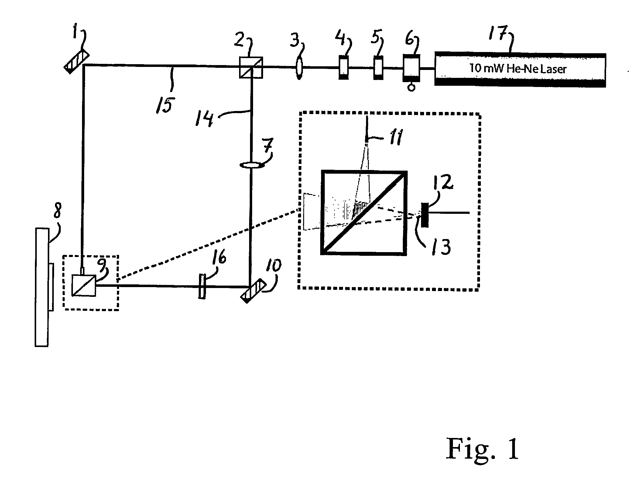
[0017]FIG. 1 is a schematic diagram of an experimental setup of a Fourier holography equipment. The equipment comprises a JDS Uniphase 10 mW He-Ne laser 17 emitting light at the wavelength of 633 nm. The light passes a shutter 6, a first polarizer 5 and a second polarizer 4. By the polarizers, the intensity of the laser beam may be adjusted. Thence, the laser beam passes a first halfwave plate 3 and reaches a polarizing beam splitter 2 dividing the beam into an object beam 14 and a reference beam 15. The object beam 14 passes a second halfwave plate 7 and is diverted 90 degrees by a mirror 10. Thence, the object beam passes an Iris diaphragm 16 and reaches a beam splitter 9. The reference beam 15 is diverted by a mirror 1 towards the beam splitter 9 and passes a GRIN lens 11, which diverts the reference beam 15 as shown in the enlarged section of FIG. 1.

[0018] An object 12 is arranged close to the beam splitter 9. The laser beam passing through the object is collected by a sensor 8...


PUM


Abstract

A method and device for determining refractive index of an object compared to a refractive index of a surrounding medium. The object is exposed to a laser object beam and the scattered light interferes with a laser reference beam to obtain a hologram. The hologram is analyzed for phase information, and based thereon, it is determined if the refractive index of the object is higher or lower than the refractive index of the surrounding medium.

Description

AREA OF INVENTION [0001] The present invention relates to a method and device for holographic refractometry useful for the comparision of refractive index between an object and a surrounding medium using digital holography. PRIOR ART [0002] A commonly known method for determination of refractive index of small inhomogenous, transparent objects is the method known as the Becke method. The Becke method involves placing the object in a medium having a known refractive index, for example a Refractive Index Liquid. The sample is arranged in a microscope and light is passed through the sample. The person using the microscope moves the focal plane upwards (or downwards). The Becke lines seem to move outwards or inwards relative to the contour of the object. The movement of the Becke lines is dependent on whether the refractive index of the object is lower or higher than the refractive index of the surrounding medium. By placing the object in several media having different refractive index ...

Claims


Application Information

Patent Timeline
IPC IPC(8): G01N21/41G01N21/43G03H1/00
CPCG03H1/0005G03H2001/0033G03H2001/0038G03H2001/045G03H2210/12
Inventor GUSTAFSSON, MATSSEBESTA, MIKAELEGELBERG, PETERLENART, THOMASPETTERSSON, SVEN-GORANBENGTSSON, BENGT
Owner PHASE HOLOGRAPHIC IMAGING PHI
Learn More