
Apparatus and method for remote inspection of a structure using a special imaging system

Inactive Publication Date: 2007-05-17
CT ZOOM TECH
View PDF21 Cites 7 Cited by
  • Summary
  • Abstract
  • Description
  • Claims
  • Application Information

AI Technical Summary

Benefits of technology

[0006] The present invention suggests fast and cost-effective systems and methods to produce comprehensive and detailed assessments of given sections of sewer systems. The present new technique produces impeccable detailed documentation to support budgetary requests and master plans. Therefore, it is possible to establish immediate inspection and cleaning priorities while obtaining a “big-picture” view of what needs to be done in the long term.

Problems solved by technology

It is sometimes necessary to inspect certain areas that are inconvenient and / or time-consuming to access.
As a result, related inspection costs become tremendous due to costs of pumping and diverting water flow before the inspection (can double the costs of inspection of a small-diameter pipe and more than quintuple it in the case of larger sewer mains).
In fact, mainly because of budgetary reasons, traditional methods are limited to inspect relatively small sections of sewer systems.
Moreover, by flushing pipes out before inspection, vital information that could actually help to pinpoint the problem could be destroyed.
Traditional imaging systems for inspection of underground conduits lack efficiency because they are not suitably accommodated for such inconvenient areas.

Method used


Image

  • Apparatus and method for remote inspection of a structure using a special imaging system
  • Apparatus and method for remote inspection of a structure using a special imaging system
  • Apparatus and method for remote inspection of a structure using a special imaging system

Examples


Embodiment Construction

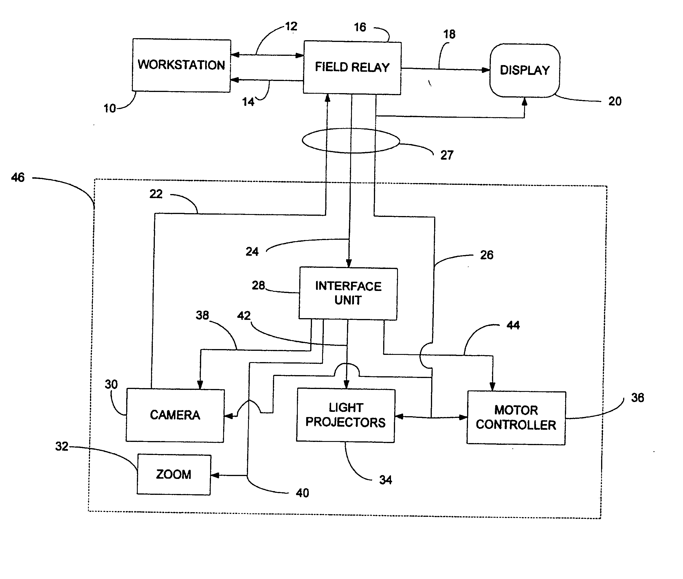
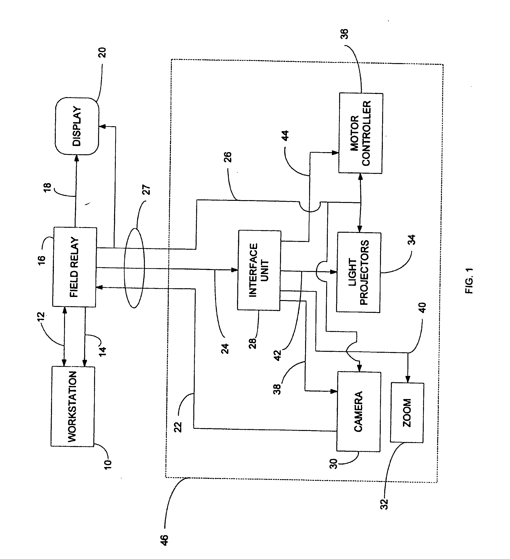
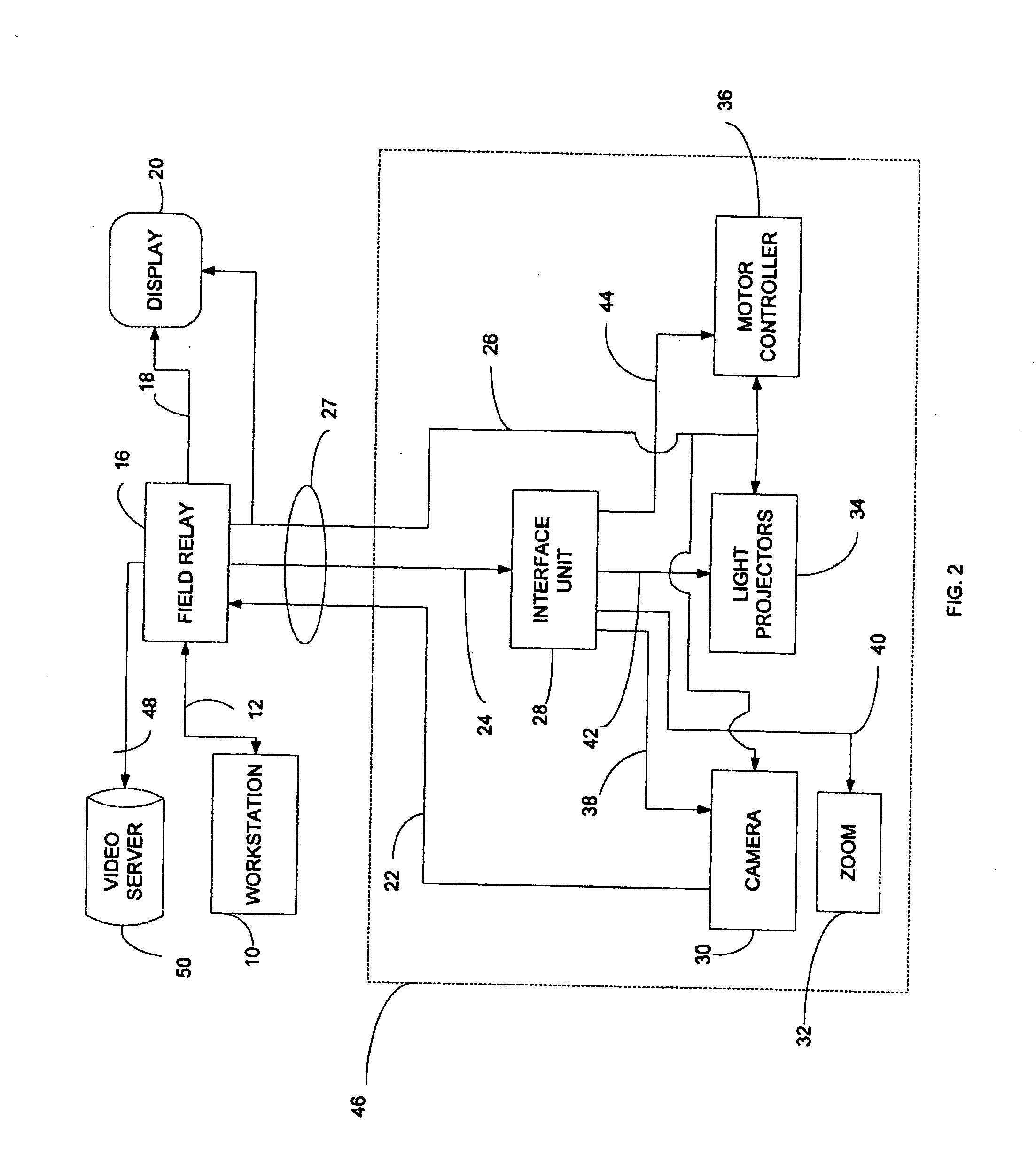
[0077] The imaging system used in the present invention is not a regular imaging system that can be hold over a shoulder but is a special imaging system mounted on a mast supported by a support member that is usually fixed to an inspection truck. For illustrative purposes, the inspection of underground conduits will be described, although the scope of the present invention in by no means limited to this application. In fact, the invention relates to the remote inspection of structures that may be examined remotely using an imaging system, such as underground conduits and railroad bridge support structures.

[0078] In the text, when it is referred to “imaging system”, it should be understood that it is referred to the part of the inspection system that is placed inside the inspecting underground conduit for imaging. The “imaging system” does not include components that do not constitute a part of the system placed inside the conduit for inspection. However, when it is referred to “ins...


PUM


Abstract

The present invention relates to inspection of underground conduits, railroad bridge support structures and other facilities that may be examined remotely, using a video camera or other imaging system. The present invention provides fast and cost-effective systems and methods to inspect such structures remotely and to produce comprehensive and detailed information about inspected structures.

Description

FIELD OF THE INVENTION [0001] The present invention generally relates to the remote inspection of areas that are difficult to reach. More specifically, the invention relates to inspection of underground conduits, railroad bridge support structures and other facilities that may be examined remotely, using a video camera or other imaging system. BACKGROUND OF THE INVENTION [0002] It is sometimes necessary to inspect certain areas that are inconvenient and / or time-consuming to access. For illustrative purposes, the inspection of underground conduits will be described, although the scope of the present invention is by no means limited to this application. Most municipalities contain a vast network of underground conduits. Periodically, these conduits must be inspected for problems such as cracks, blockage, build-up, and root infiltration. If a problem is detected, detailed images must be obtained to facilitate planning to remedy the situation. [0003] Conventional sewer inspection method...

Claims


Application Information

Patent Timeline
IPC IPC(8): H04N5/232
CPCH04N5/23203H04N23/66
Inventor LORTIE, ALAINBLIER, SEBASITEN
Owner CT ZOOM TECH
Learn More