
Vehicle decorative component

a technology for decorative components and vehicles, applied in vehicular safety arrangments, using reradiation, instruments, etc., can solve the problems of improper operation of radar devices, interference of radar waves, and increased manufacturing costs, so as to improve the transparency of radar waves

Active Publication Date: 2007-05-17
TOYODA GOSEI CO LTD
View PDF3 Cites 29 Cited by
  • Summary
  • Abstract
  • Description
  • Claims
  • Application Information

AI Technical Summary

Benefits of technology

[0006] Accordingly, it is an objective of the present invention to provide an inexpensive vehicle decorative component that has an improved transparency of radar waves.

Problems solved by technology

If a decorative component such as a metal emblem is located in the path of radar waves transmitted from the radar device, the radar waves are interfered by the component.
This causes the radar device to function improperly.
Since the metal film of Japanese Laid-Open Patent Publication No. 2002-135030 is formed of a special metal, or indium, which has a high transparency to radar waves, the manufacturing costs are increased.
Thus, the interface between the back layer and the protective layer is likely to refract and reflect radar waves.
As a result, the radar waves cannot readily pass through the decorative component of the publication No. 2004-309322.

Method used


Image

  • Vehicle decorative component
  • Vehicle decorative component
  • Vehicle decorative component

Examples


Embodiment Construction

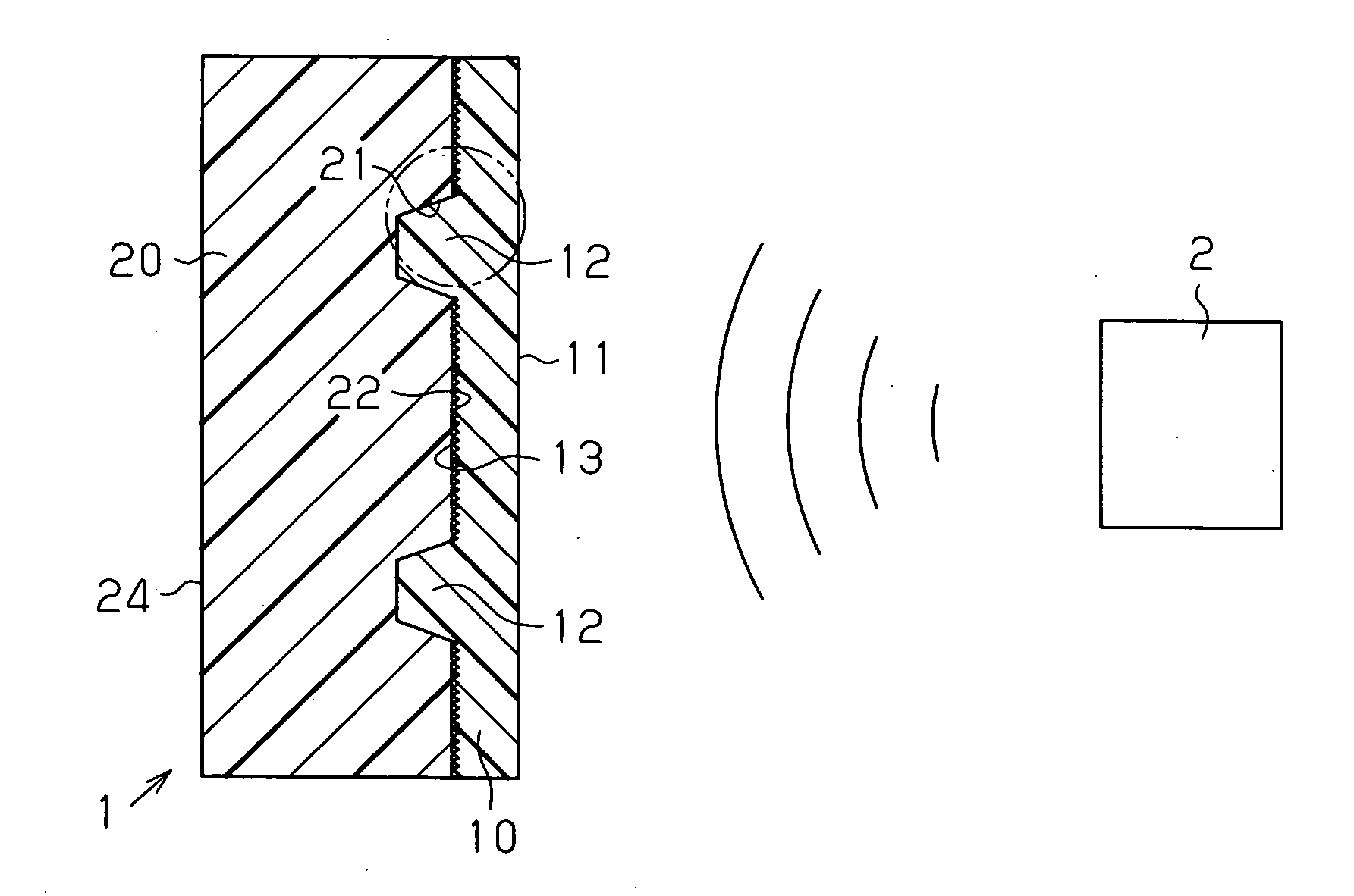
[0016] One embodiment of the present invention will now be described with reference to FIGS. 1A to 2.

[0017] In FIG. 1A, the left end is defined as a front side of a vehicle, and the right end is defined as a rear side of the vehicle.

[0018] As shown in FIG. 1A, a radar device 2 is located rearward of a vehicle decorative component 1 and in the engine compartment. Specifically, the radar device 2 is located in a portion that corresponds to the radiator grille. The radar device 2 is used for emitting high frequency electromagnetic waves such as millimeter waves forward of the vehicle, thereby measuring the distance with a preceding vehicle or an obstacle. The decorative component 1 is attached to the vehicle to be located in a path of radar waves emitted by the radar device 2. The decorative component 1 is provided, for example, at the radiator grille.

[0019] As shown in FIG. 1A, the decorative component 1 has a two-layer structure. Specifically, the decorative component 1 includes a...


PUM


Abstract

A radar device is placed rearward of a vehicle decorative component in a vehicle. The decorative component is located in the path of radar waves emitted from the radar device, and has a two-layer structure with a back layer and a protective layer. The protective layer is made of a transparent resin material, and the back surface of the protective layer contacts the front surface of the back layer. The back layer is made of a resin material. The front surface of the back layer includes a front contact surface on which ground pattern is formed. The protective layer and the back layer have the same refractive index. Thus, the decorative component has an improved transparency of radar waves.

Description

BACKGROUND OF THE INVENTION [0001] The present invention relates to a decorative component for a vehicle having a radar device. [0002] Conventionally, some vehicles are equipped with a radar device located on the back of the front grille for measuring the distance with another vehicle or an obstacle by using radar waves. If a decorative component such as a metal emblem is located in the path of radar waves transmitted from the radar device, the radar waves are interfered by the component. This causes the radar device to function improperly. [0003] Accordingly, for example, Japanese Laid-Open Patent Publication No. 2002-135030 discloses a vehicle decorative component that includes a back coating plate made of a material transparent to radar waves, an outer surface coating plate made of an optically transparent material that is also transparent to radar waves, and a metal film made of indium located between the back coating plate and the outer surface coating plate. The indium film is...

Claims


Application Information

Patent Timeline
Patent Type & Authority Applications(United States)
IPC IPC(8): H01Q1/32H01Q1/00
CPCB60R13/005B60R19/483H01Q1/3233H01Q1/422H01Q1/44G01S2013/9389G01S2013/93271G01S2013/93275
Inventor FUJII, TETSUYATOTANI, CHIHARUOBA, TATSUYA
Owner TOYODA GOSEI CO LTD
Learn More