Eureka AIR delivers breakthrough ideas for toughest innovation challenges, trusted by R&D personnel around the world.

Merchandise display rack

a technology for display racks and merchandise, applied in the direction of racks, display hangers, domestic applications, etc., can solve the problems of affecting the viewing experience of products on the lower shelves, affecting the use of the downwardly inclined shelves, and affecting the quality of the produ

Inactive Publication Date: 2007-05-17
EXCELL PRODUTS
View PDF31 Cites 96 Cited by
  • Summary
  • Abstract
  • Description
  • Claims
  • Application Information

AI Technical Summary

Benefits of technology

[0007] In one aspect of the present invention, a merchandise display rack for feeding merchandise or products arranged in rows on a shelf to the front of the shelf is provided. Broadly, the merchandise display rack includes a pusher frame and a pusher plate assembly. The pusher frame is characterized as having a front end, a rear end, a first sidewall, a spatially disposed second sidewall and a product receiving space formed between the first and second sidewalls for receiving a row of merchandise or product. If the merchandise display rack is to be used in combination with a wire shelf, the pusher frame may also include a bottom for providing a smooth surface over which the merchandise can travel as the merchandise is moved through the product receiving space of the merchandise display rack. A stop plate assembly is removably connected to the front end of the merchandise display rack for preventing forward movement of the product past the stop plate assembly and to secure the forward most merchandise in the row of merchandise in a stable position.
[0018] Another object of the present invention, while achieving the before-stated objects, is to provide a merchandise display rack which is economical to manufacture and substantially maintenance free.

Problems solved by technology

However, the use of the downwardly inclined shelves are often not satisfactory because the merchandise at times does not slide smoothly down the shelf and can fall over thereby jamming the row of merchandise from feeding properly.
Also, customers may have difficulty in viewing products on lower shelves when the shelves are downwardly inclined.
However, the prior art devices have suffered from the disadvantage in that it is difficult to adjust such spring loaded pusher systems so that such systems accommodate merchandise of different sizes and weights.

Method used


Image

  • Merchandise display rack
  • Merchandise display rack
  • Merchandise display rack

Examples


Embodiment Construction

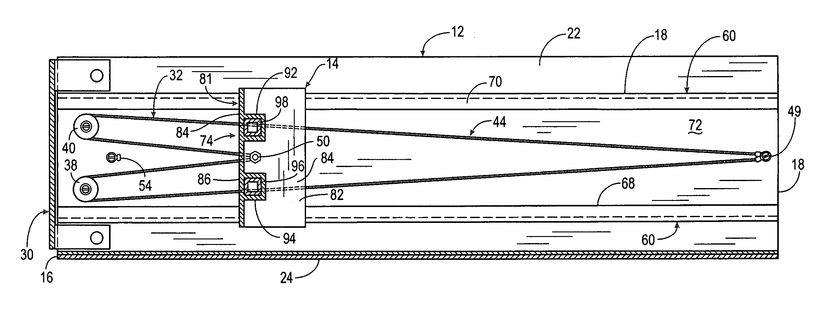
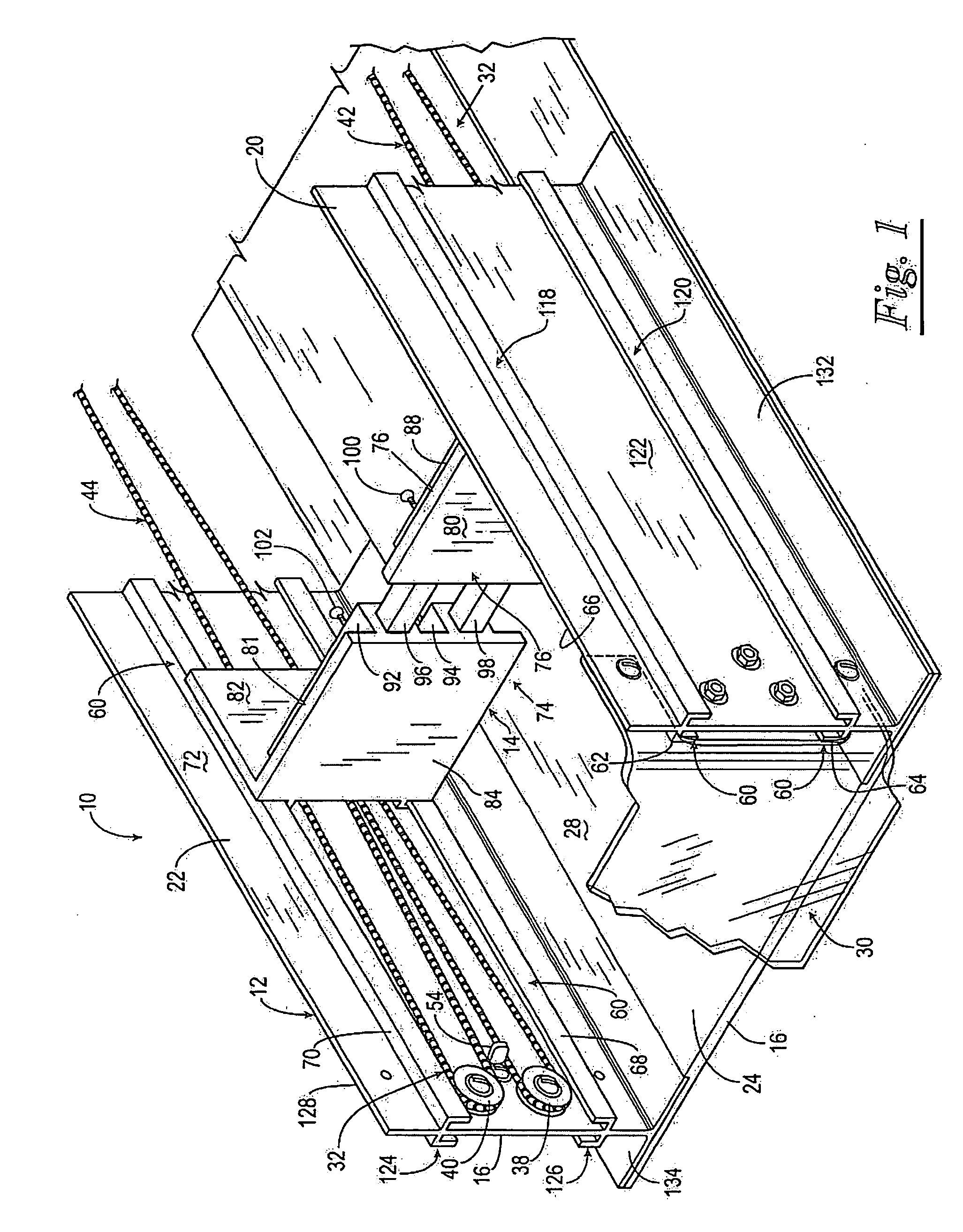
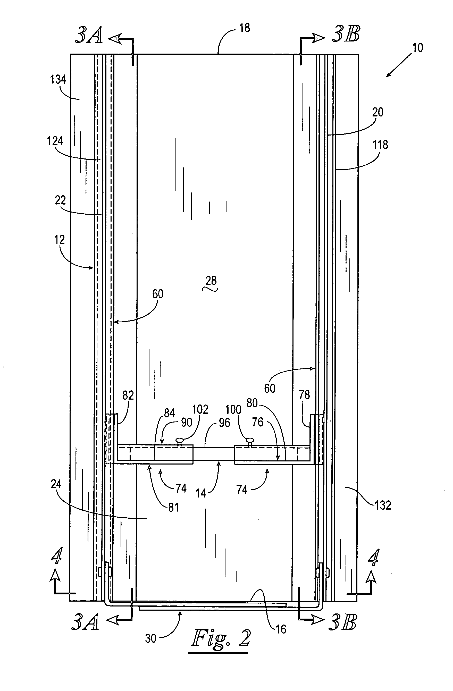
[0031] Referring now to the drawings, and more particularly to FIGS. 1 and 2, shown therein is a merchandise display rack 10 constructed in accordance with the present invention. The merchandise display rack 10 functions to feed a row of merchandise or product forward on a store shelf as merchandise or product at the front of the row of merchandise is removed by a customer. The merchandise display rack 10 includes a pusher frame 12 and a pusher plate assembly 14. The pusher frame 12 is characterized as having a front end 16, a rear end 18 (FIG. 2), a first sidewall 20, a spatially disposed second sidewall 22 and a product receiving space 24 formed between the first and second sidewalls 20 and 22 for receiving a row of merchandise or product 26 (FIGS. 7 and 8). If the merchandise display rack 10 is used in combination with a wire shelf, the pusher frame 12 may also include a bottom 28 for providing a smooth surface over which the merchandise or product can travel as the merchandise o...


PUM


Abstract

A merchandise display rack is provided for displaying a row of merchandise on a store shelf and feeding the row of merchandise forward on a store shelf as merchandise at the front of the row of merchandise is removed by a customer. The merchandise display rack includes a pusher frame, a pusher plate assembly and a pusher plate biasing assembly supported on opposing sidewalls of the display rack and connected to the pusher plate assembly.

Description

CROSS REFERENCE TO RELATED APPLICATION [0001] This application claims benefit under 35 U.S.C. 119(e) of U.S. Ser. No. 60 / 737,819, filed Nov. 17, 2005.BACKGROUND OF INVENTION [0002] 1. Field of Invention [0003] The present invention relates to a merchandise display rack, and more particularly but not by way of limitation, to a merchandise display rack for feeding a row of merchandise forward on a store shelf as merchandise at the front of the row of merchandise is removed by a customer. [0004] 2. Brief Description of the Prior Art [0005] Products or merchandise of various types and sizes are commonly stored on display shelves in stores so that customers can see the products or merchandise and select products or merchandise for purchase. In some instances, shelves are inclined downwardly from the rear to the front so that the merchandise can be gravity fed to the front of the shelf. However, the use of the downwardly inclined shelves are often not satisfactory because the merchandise ...

Claims


Application Information

Patent Timeline
Patent Type & Authority Applications(United States)
IPC IPC(8): A47F1/04
CPCA47F1/126
Inventor MEDCALF, MERLE D.MEDCALF, MICHAEL D.
Owner EXCELL PRODUTS
Why Eureka
Eureka Blog
Learn More