
Multifunctional robot tool

a multi-functional, robot technology, applied in the field of multi-functional tools, can solve the problems of increasing the time required for the robot to travel back and forth, reducing the overall efficiency of operation, and reducing the efficiency of the overall operation, so as to improve the efficiency of the robot, reduce the amount of time, and improve the effect of single-function tools

Inactive Publication Date: 2007-05-17
FOSTER-MILLER
View PDF70 Cites 28 Cited by
  • Summary
  • Abstract
  • Description
  • Claims
  • Application Information

AI Technical Summary

Benefits of technology

[0009] It is a further object of this invention to provide such a tool which reduces or eliminates the necessity to retrieve a robot in order to change tools.
[0011] The subject invention results from the realization that improvement over single function tools can be achieved by a tool having multiple capabilities, and which does not require components to be changed in order to shift from one function to another. The invention results from the further realization that, in one example, such a multifunctional tool can be used with a remote control robot to increase the efficiency of the robot, and thus decrease the amount of time that individuals near the robot's working area are exposed to danger.

Problems solved by technology

Typically multiple end effectors which must be changed are heavy and complex.
Thus, a robot which requires the operator to bring the robot back to change tools reduces the overall efficiency of the operation.
Additionally, the time required for the robot to travel back and forth extends the time that the explosive device presents a hazard.
Also, when operations are carried out in a hostile environment, the amount of time the operator and other personnel are exposed to potential attack is increased.

Method used


Image

  • Multifunctional robot tool
  • Multifunctional robot tool
  • Multifunctional robot tool

Examples


Embodiment Construction

[0023] Aside from the preferred embodiment or embodiments disclosed below, this invention is capable of other embodiments and of being practiced or being carried out in various ways. Thus, it is to be understood that the invention is not limited in its application to the details of construction and the arrangements of components set forth in the following description or illustrated in the drawings. If only one embodiment is described herein, the claims hereof are not to be limited to that embodiment. Moreover, the claims hereof are not to be read restrictively unless there is clear and convincing evidence manifesting a certain exclusion, restriction, or disclaimer.

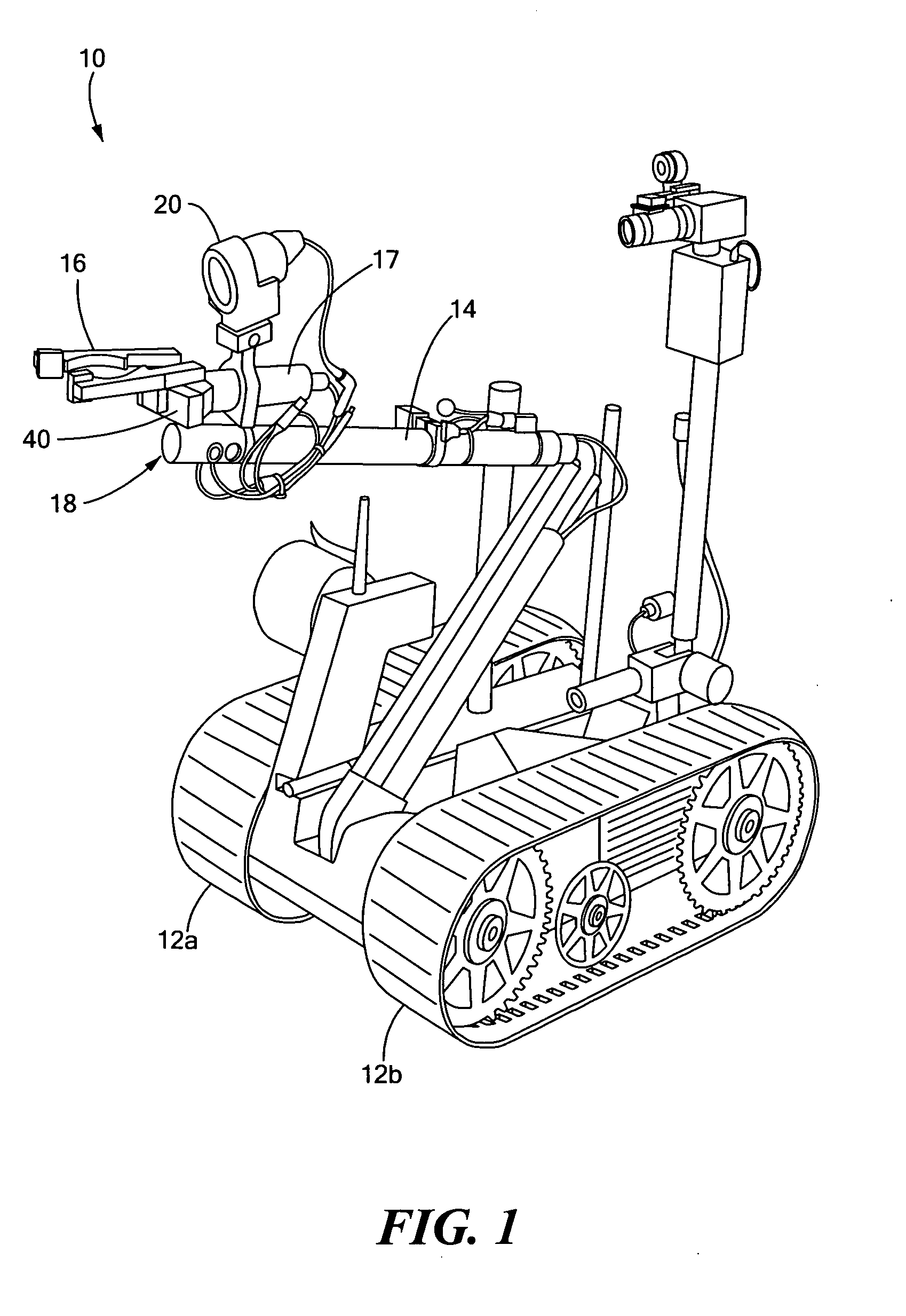
[0024] As discussed in the Background section above, robots have been widely used in place of human action when harmful and / or hazardous environmental conditions are present. Remote control robots, such as the Foster-Miller Talon™ robot, have been utilized when conditions necessitate operating the robot from afar, for exa...


PUM


Abstract

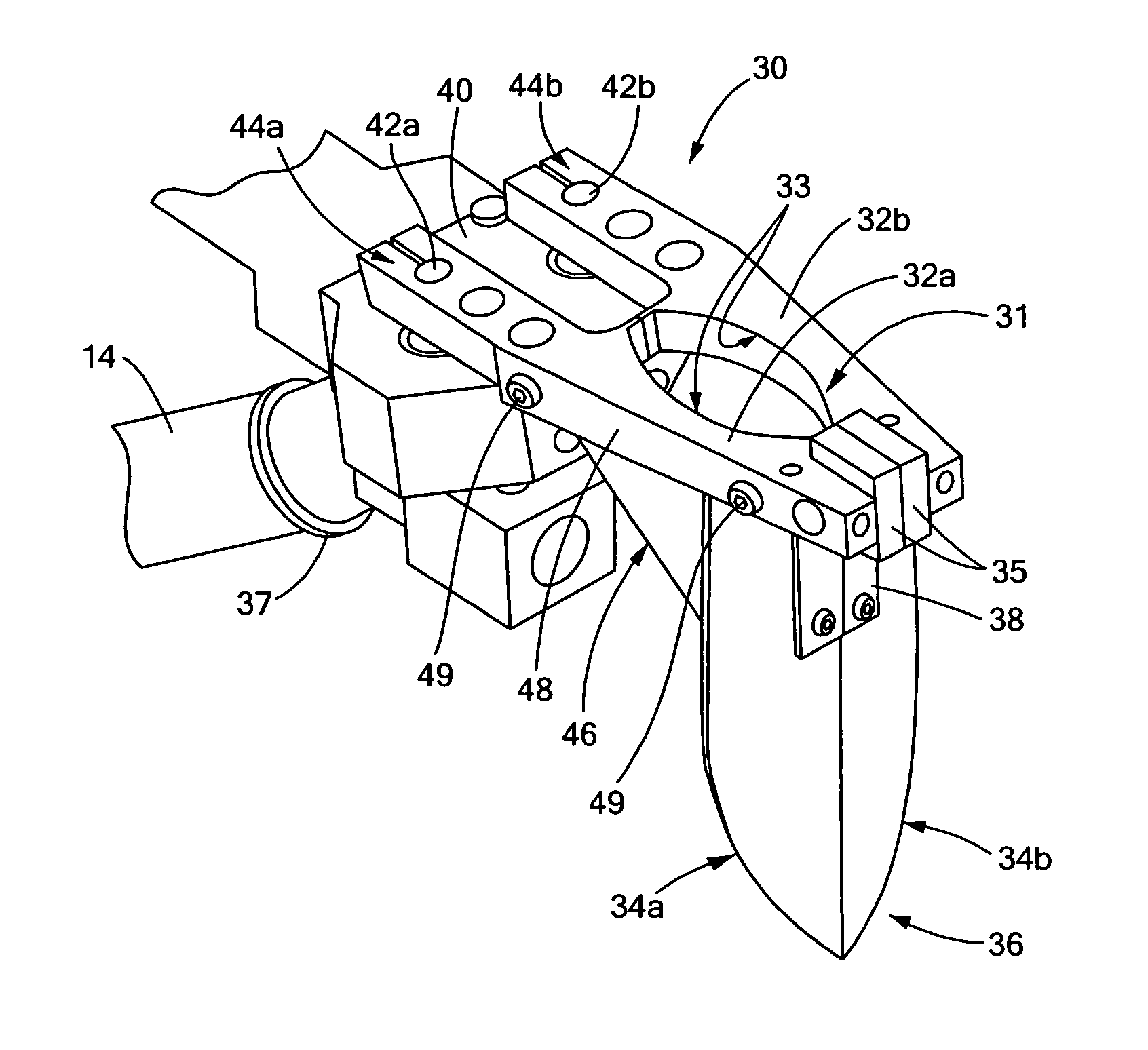
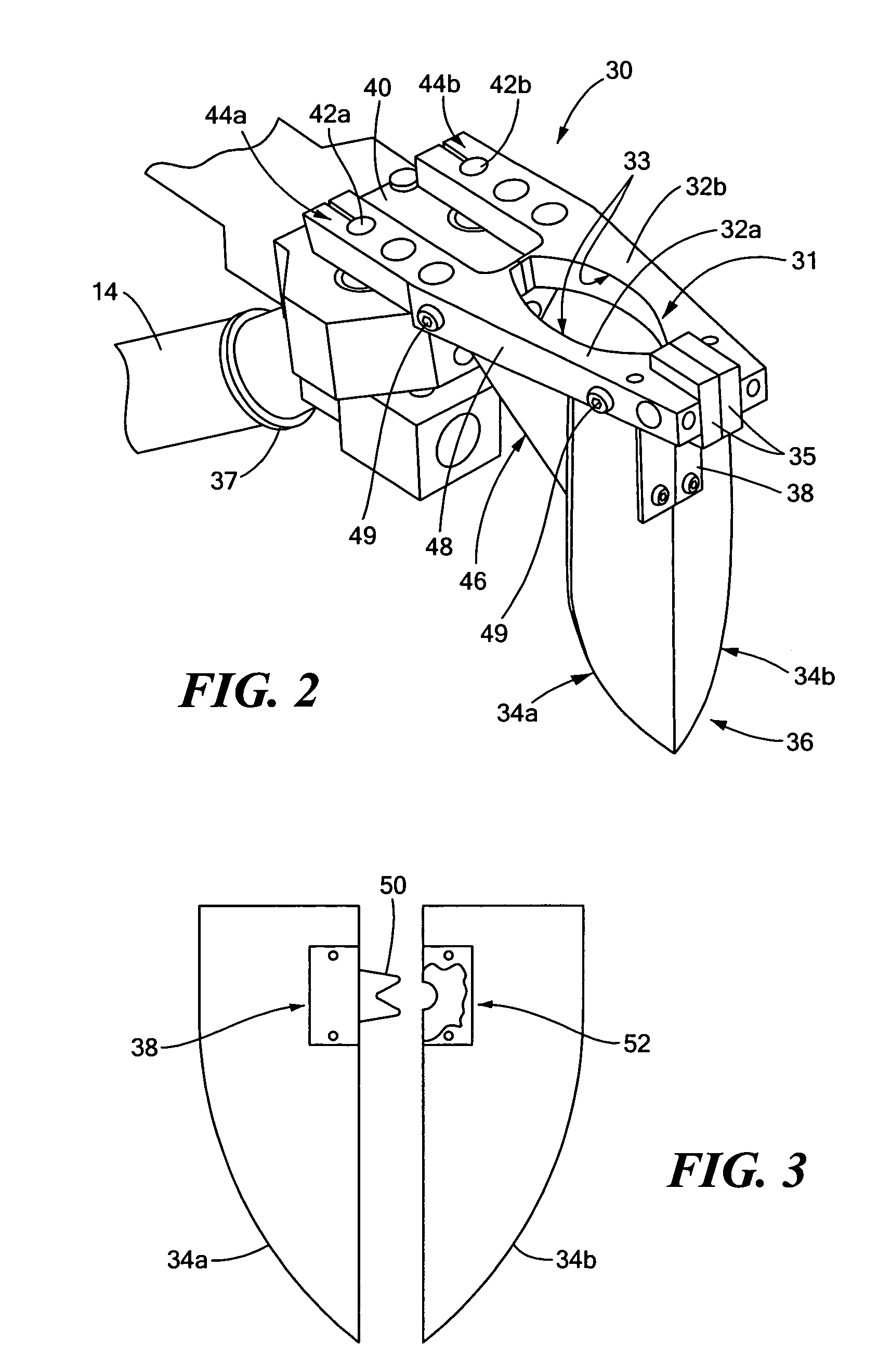
A multifunctional robot tool includes a pair of driven fingers configured as a gripper and a blade depending from each finger. The blades are configured as a digging spade when closed together by the fingers. A knife is associated with at least one blade for cutting wire.

Description

RELATED APPLICATIONS [0001] This application claims the benefit of and priority to U.S. Provisional Patent Application Ser. No. 60 / 736,612 filed Nov. 14, 2005 entitled Robot Technology.FIELD OF THE INVENTION [0002] This subject invention relates to a multifunctional tool, and in one example such a tool for a remote control robot. BACKGROUND OF THE INVENTION [0003] On the battlefield or otherwise, small, maneuverable, lightweight, remote control robots can be used to minimize human exposure to potentially lethal environments and situations. In one example, remotely controlled robots, such as the Foster-Miller Talon™ robot, have been widely used to detect and disable explosive devices and ordnances in the field including roadside bombs in Iraq. One advantage of using a remotely controlled robot is that it eliminates the need for personnel to approach the explosive device. The individuals controlling the robot may remain at a relatively safe distance, usually a few hundred meters from ...

Claims


Application Information

Patent Timeline
Patent Type & Authority Applications(United States)
IPC IPC(8): A01B49/02
CPCF41C27/04F41C27/20F41H7/005F41H11/11F41H11/20F41H11/28
Inventor DOHERTY, BRIAN J.OSBORNE, MICHAEL W.REYNOLDS, WILLIAM C.HUG, HANS A.DESMEULE, NATHAN
Owner FOSTER-MILLER
Learn More