
Self-calibrating oversampling electromechanical modulator and self-calibration method

a self-calibration and electromechanical modulator technology, applied in the direction of acceleration measurement, speed/acceleration/shock measurement devices, instruments, etc., can solve the problem of unavoidable mobile mass influence by position offset, inability to ensure that the precision will remain unaltered over time, and inability to balance the capacitances of capacitors

Inactive Publication Date: 2007-05-17
STMICROELECTRONICS SRL
View PDF12 Cites 17 Cited by
  • Summary
  • Abstract
  • Description
  • Claims
  • Application Information

AI Technical Summary

Problems solved by technology

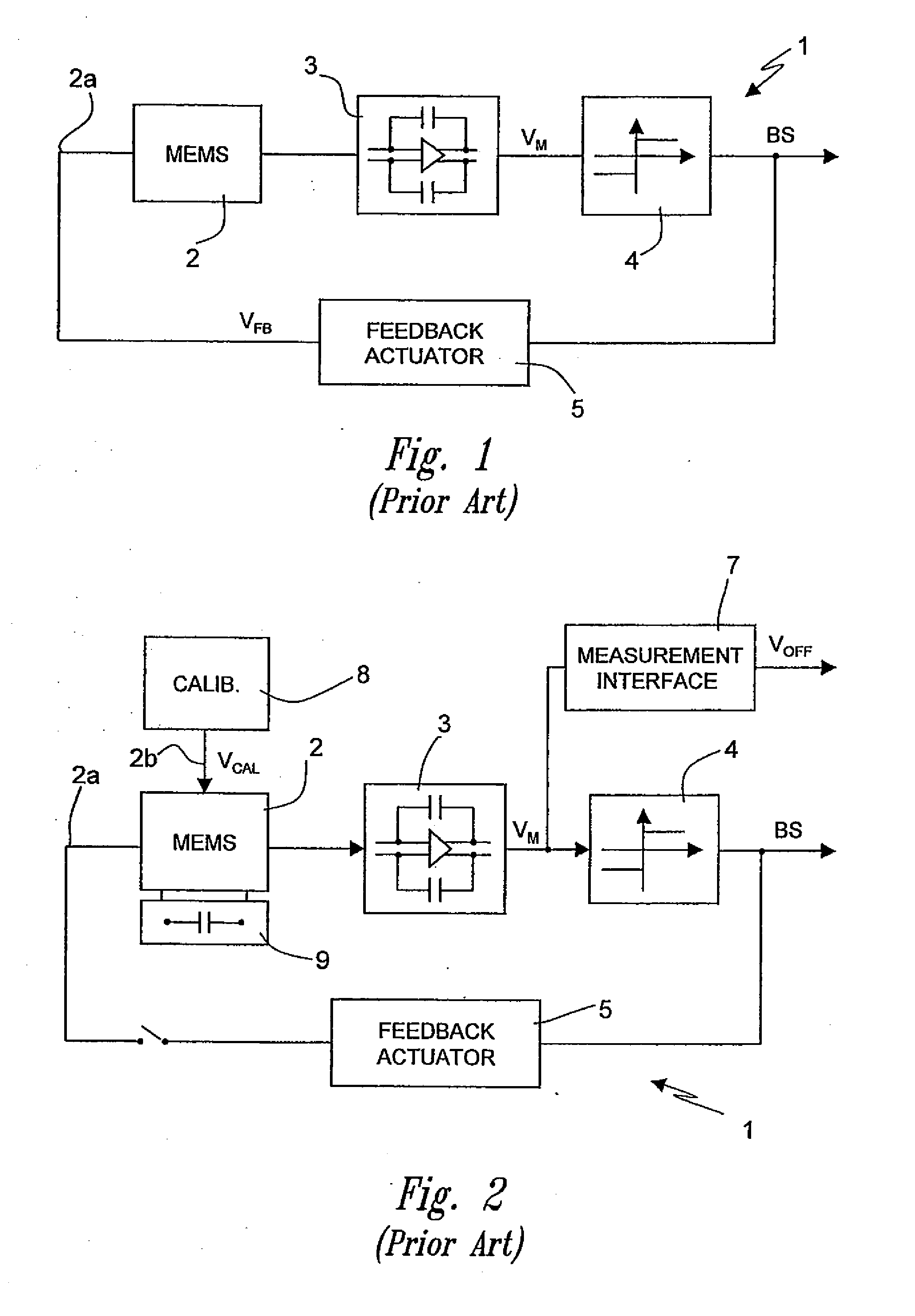
When a sensor is excited, its mobile mass is displaced and there is an unbalance between the capacitances of the capacitors, which can be detected at the sensing terminals.
In actual fact, notwithstanding the extremely high precision of the micromachining techniques used for building MEMS sensors, it is unavoidable that the mobile mass is affected by a position offset; consequently, also in resting conditions the mobile arms are not equidistant from the fixed arms.
As a result, MEMS sensors have an intrinsic capacitive unbalance which, in an electromechanical modulator, causes an offset of the bitstream BS (in practice, the average of the bitstream BS is not zero).
In the first place, calibration can be performed only in the factory, and consequently it cannot be ensured that the precision will remain unaltered over time.
In addition, MEMS sensors are extremely sensitive and are able to detect even minimal vibrations.
Consequently, it is very difficult to create a condition of effective absence of stress in which a precise calibration can be performed.

Method used


Image

  • Self-calibrating oversampling electromechanical modulator and self-calibration method
  • Self-calibrating oversampling electromechanical modulator and self-calibration method
  • Self-calibrating oversampling electromechanical modulator and self-calibration method

Examples


Embodiment Construction

[0033] The invention finds advantageous application in all cases in which a micro-electromechanical sensor is used for detecting a quantity the frequency spectrum of which does not include the continuous component (i.e., it does not comprise a zero frequency). For example, an electromechanical modulator according to the present invention can be used for controlling the position of R / W heads for reading and writing hard disks in electronic computers.

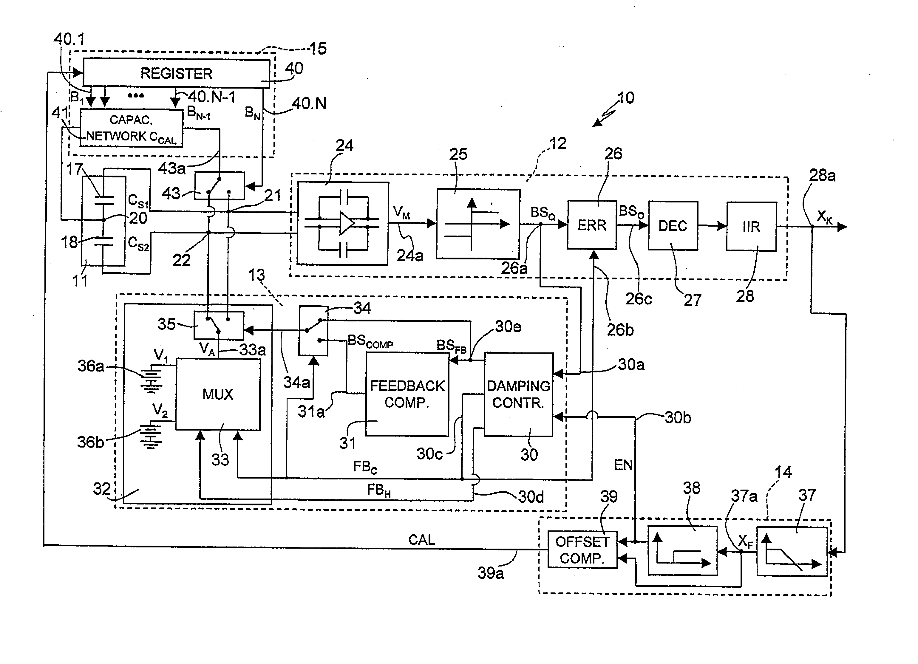
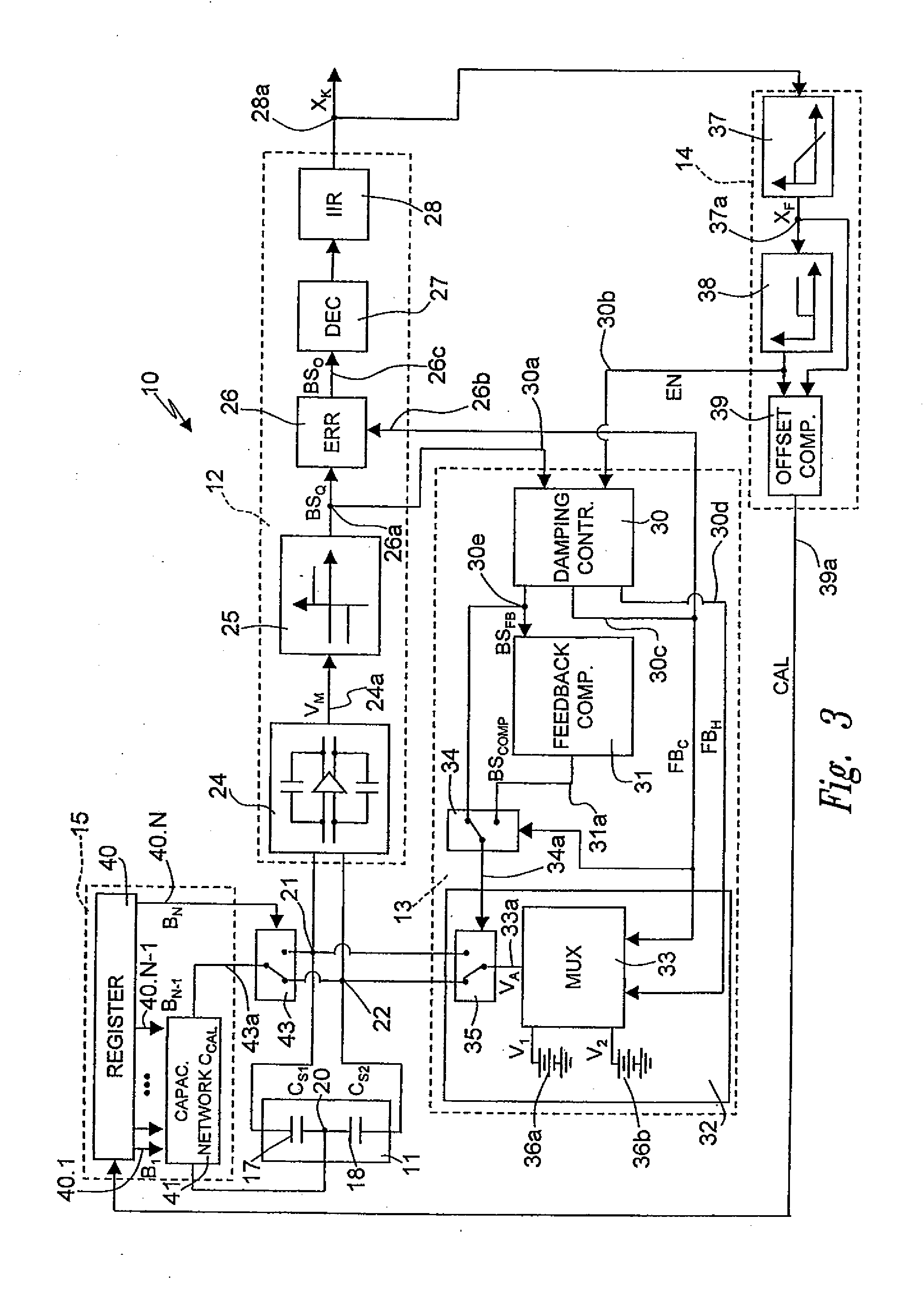
[0034] With reference to FIG. 3, an oversampling electromechanical modulator 10 comprises a MEMS sensor 11, a converter stage 12, a feedback stage 13, an offset-sensing stage 14, and a calibration circuit 15.

[0035] The MEMS sensor 11, the structure of which is shown in FIG. 4, in the embodiment herein described is a linear accelerometer for detection of an acceleration A and comprises a stator 100 and a mobile mass 101. The stator 100 and mobile mass 101, which are made of an appropriately doped semiconductor material, are connected tog...


PUM


Abstract

An oversampling electromechanical modulator, including a micro-electromechanical sensor which has a first sensing capacitance and a second sensing capacitance and supplies an analog quantity correlated to the first sensing capacitance and to the second sensing capacitance; a converter stage, which supplies a first numeric signal and a second numeric signal that are correlated to the analog quantity; and a first feedback control circuit for controlling the micro-electromechanical sensor, which supplies an electrical actuation quantity correlated to the second numeric signal. The electromechanical modulator moreover includes a second feedback control circuit for calibrating the micro-electromechanical sensor, which includes an offset-sensing circuit that can be activated by the first numeric signal, and a programmable calibration circuit, having a programmable calibration capacitance, which is connected to the micro-electromechanical sensor and is controlled by the offset-sensing circuit for balancing of the first sensing capacitance and second sensing capacitance.

Description

CROSS-REFERENCE TO RELATED APPLICATION [0001] This application is a divisional of U.S. patent application Ser. No. 10 / 198,720, filed Jul. 16, 2002, now pending, which application is incorporated herein by reference in its entirety.BACKGROUND OF THE INVENTION [0002] 1. Field of the Invention [0003] The present invention relates to a self-calibrating oversampling electromechanical modulator and to a self-calibration method. [0004] 2. Description of the Related Art [0005] As is known, the use of micro-electromechanical-system (MEMS) sensors with differential capacitive unbalance has been proposed for building, for example, linear or rotational accelerometers and pressure sensors. [0006] In particular, MEMS sensors of the above-mentioned type comprise a fixed body (stator) and a mobile mass, which are generally of an appropriately doped semiconductor material, are connected together by elastic-suspension elements (springs) and are constrained in such a way that the mobile mass has, with...

Claims


Application Information

Patent Timeline
Patent Type & Authority Applications(United States)
IPC IPC(8): G01R17/14G02B26/08
CPCG02B26/0841
Inventor LASALANDRA, ERNESTOPASOLINI, FABIOGRECO, VALERIA
Owner STMICROELECTRONICS SRL
Learn More