
Self-expanding stent delivery system

a stent and self-expanding technology, applied in the field of self-expanding stent delivery systems, can solve the problem of excessive and achieve the effect of reducing the friction force between the stent and the outer sheath

Inactive Publication Date: 2007-05-10
ABBOTT LAB VASCULAR ENTERPRISE
View PDF6 Cites 11 Cited by
  • Summary
  • Abstract
  • Description
  • Claims
  • Application Information

AI Technical Summary

Benefits of technology

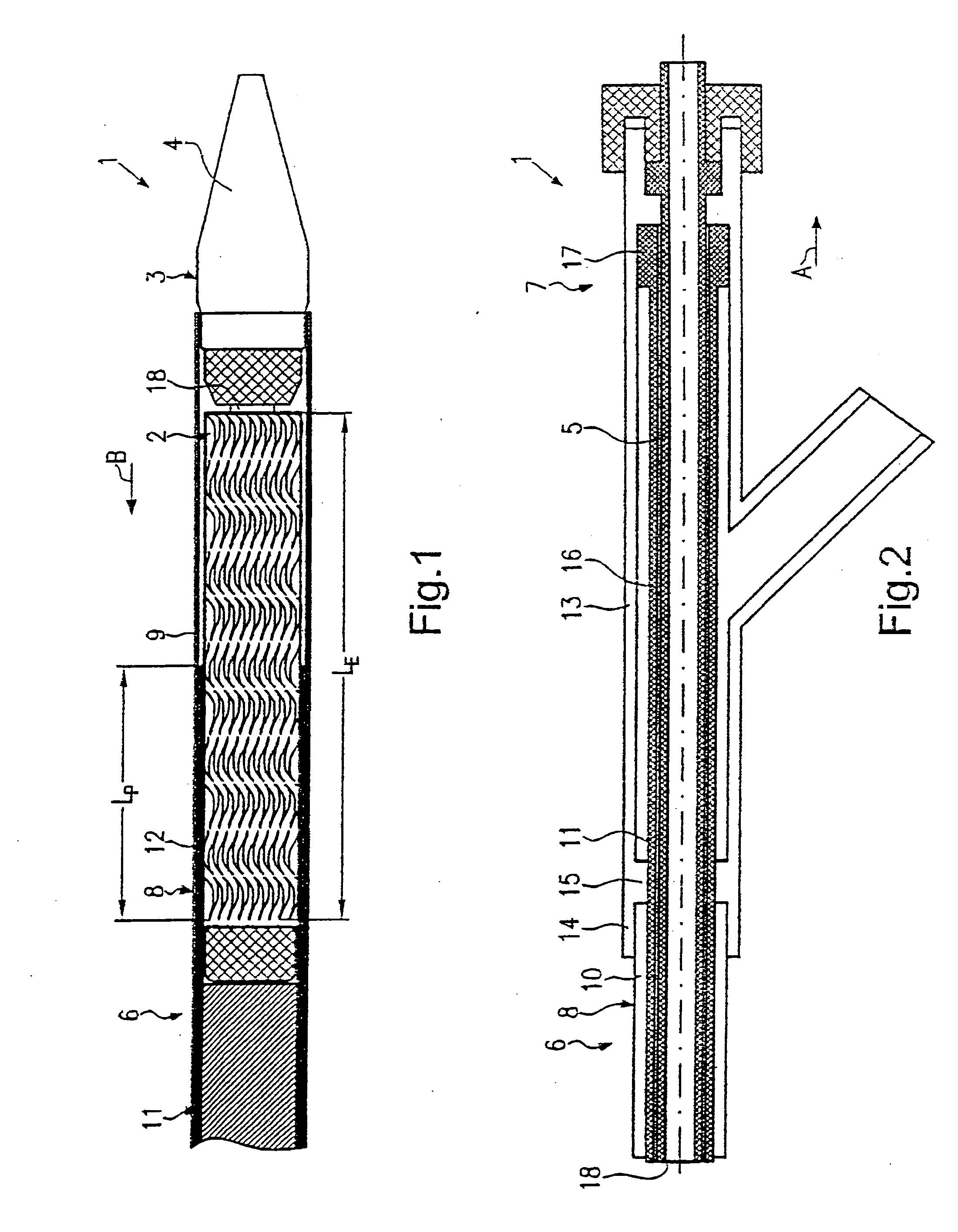
"The present invention provides a self-expanding stent delivery system that can smoothly retract the outer sheath and deploy the stent with low retraction forces. This is achieved by a simple and effective arrangement where the outer sheath is divided into an outer tube and a separate inner tube, with the stent only partly surrounded by the inner tube. The system also includes stop members that engage each other to allow for easy and accurate positioning of the stent. The materials of the tubes are chosen from combinations of low friction resistance materials."

Problems solved by technology

Known delivery systems suffer, however, from the draw-back that the retraction forces are often too high, especially in cases where the stents are covered with layers made from body-compatible materials or the like so that the friction forces between the stent and the outer sheath may become excessively high.

Method used


Image

  • Self-expanding stent delivery system
  • Self-expanding stent delivery system
  • Self-expanding stent delivery system

Examples


second embodiment

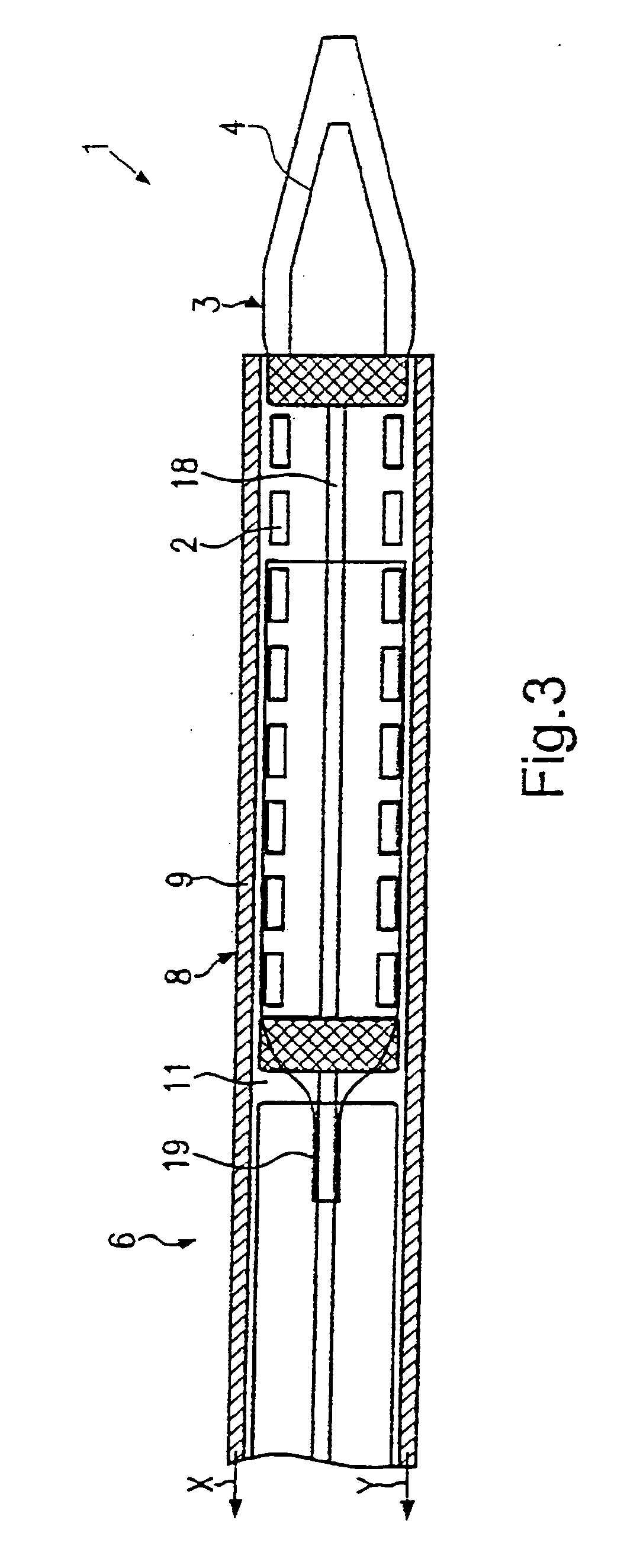
[0033]FIG. 3 depicts a second embodiment of a delivery system 1 according to the present invention. In view of the similarity between the first and second embodiments, the parts of the second embodiment that are identical or similar to the parts of the first embodiment will be given the same reference numerals as the parts of the first embodiment. Moreover, the descriptions of the parts of the second embodiment that are identical or similar to the parts of the first embodiment of FIGS. 1 and 2 may be omitted for the sake of brevity. Also, the proximal end portion illustrated in FIG. 2 is used with of the self-expanding stent delivery system of this second embodiment with slight modifications to accommodate the differences between the first and second embodiments.

[0034] The basic difference between the embodiments of FIG. 1 and FIG. 3 is to be seen in the fact that the inner tube 11 is fixed at a fixing portion 19 to the shaft 18 shortly after the stent 2 as seen in the direction of...


PUM


Abstract

A stent delivery system delivers a self-expanding stent to a predetermined location in a body lumen. The delivery system has a catheter body, a retractable outer sheath and a proximal retraction handle connected to a proximal end of the catheter body. The catheter body carries the stent near a distal end of the catheter body for transporting the stent for deployment. The sheath surrounds and contains the stent in a delivery configuration where the stent has a reduced radius along its entire axial length. The sheath has an outer tube a separate inner tube. The outer tube has a distal end portion surrounding the stent along its entire length and a proximal end portion connected to the retraction handle. The inner tube is disposed concentrically within the outer tube and has a distal end portion surrounding the stent only along a part of its entire length.

Description

BACKGROUND OF THE INVENTION [0001] 1. Field of the Invention [0002] The present invention generally relates to a self-expanding stent delivery system for delivering a self-expanding stent. [0003] 2. Background Information [0004] Delivery systems for deploying endovascular stent grafts, self-expanding stents or balloon expandable stents are well-known in the field of medical technology. One example of a stent delivery system for delivering a self-expanding stent is disclosed in International Patent Publication No. WO 98 / 23241, which corresponds to U.S. Pat. No. 5,968,052. [0005] As has been explained in the before-mentioned citation a self-expanding stent is a stent which expands from a compressed delivery position to its original diameter when released from the delivery device, exerting radial force on the constricted portion of the body lumen to re-establish patency. One common self-expanding stent is manufactured of nitinol, a nickel-titanium shape memory alloy, which can be forme...

Claims


Application Information

Patent Timeline
Patent Type & Authority Applications(United States)
IPC IPC(8): A61F2/06A61F2/95A61F2/966
CPCA61F2/95A61F2/966
Inventor RUETSCH, OLIVER
Owner ABBOTT LAB VASCULAR ENTERPRISE
Learn More