Eureka AIR delivers breakthrough ideas for toughest innovation challenges, trusted by R&D personnel around the world.

Dural Knife with Foot Plate

a technology of a foot plate and a blade blade, which is applied in the field of surgical instruments, can solve the problems of cranial nerves and the risk of injury of the underlying neurovascular structure, and achieve the effect of a safer dura opening

Inactive Publication Date: 2007-05-10
UNIV OF SOUTH FLORIDA
View PDF62 Cites 5 Cited by
  • Summary
  • Abstract
  • Description
  • Claims
  • Application Information

AI Technical Summary

Benefits of technology

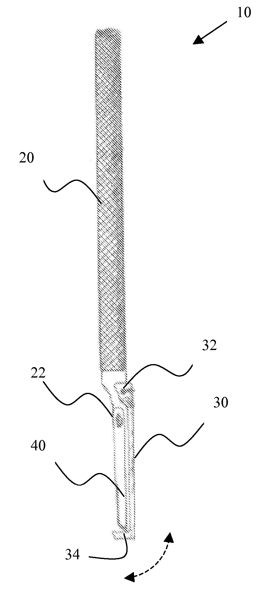
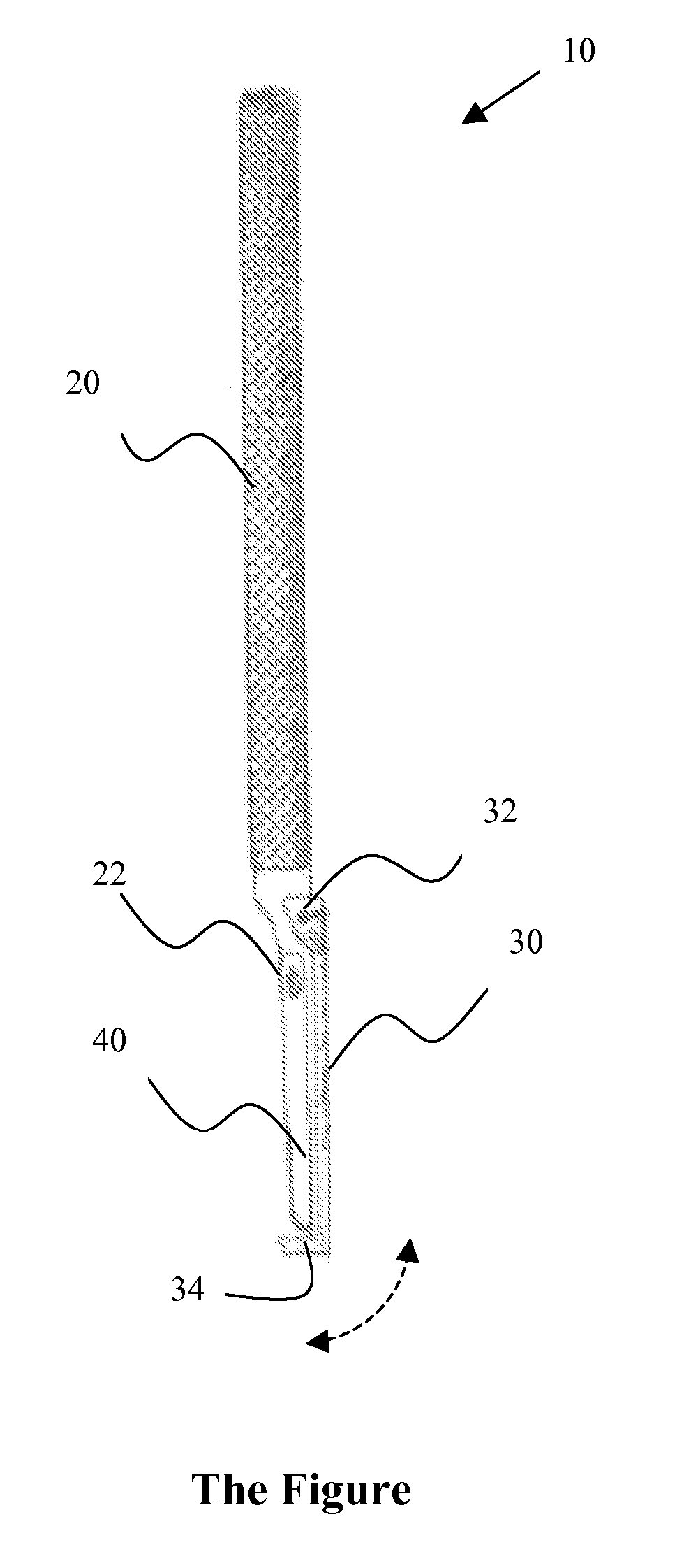
[0004] A dural knife with a protective foot-plate for use in surgical procedures. The dural knife includes a movable foot-plate disposed on an end of the scalpel in proximity to the blade. The foot plate uses a hinge joint to attach to the handle at a region near the attachment of a blade to the handle. The foot plate has a ball and socket locking mechanism. The foot-plate can be rotated 90 degrees outward to apply the blade then locked back in place. The device allows cutting of the dural meningeal layer while retracting it away from underlying neurovascular structures and thus protecting them. The device is generally made of stainless steel with a serrated handle and tapered tip with an attached, removable sharp blade. A small dural incision is made to introduce the foot plate underneath. The dura is elevated and divided between the foot plate and the sharp blade. The new device will allow safer opening of the dura in regular cranial and spinal neurosurgical procedures. In complex cranial surgery, it is extremely beneficial in dealing with dural membranes and ligaments along delicate neurovascular structures.

Problems solved by technology

Both techniques carry the risk of injury to underlying neurovascular structures by either the sharp blade or the scissors tips.
Dividing dural sleeves around cranial nerves may subject them to the risk of injury in the absence of protection from sharp cutting edges.

Method used


Image

  • Dural Knife with Foot Plate
  • Dural Knife with Foot Plate

Examples


Embodiment Construction

[0009] The disclosed invention is a dural knife having a protective foot plate. The protective foot plate facilitates the cutting of the dural meningeal layer while protecting the underlying neurovascular structures. The invention will be further described by way of the following non-limiting example.

[0010] The dural knife is a surgical device supplied with a protective foot-plate. The portion of the device having the blade and protective-foot plate can be placed through a small incision between the dural layer and underlying neurovascular structures. The dura can then be divided between the sharp edge of the blade and the foot plate. The device can replace the current techniques of dural opening for both cranial and spinal neurosurgical procedures. It will add safety to the dural opening in regular neurosurgical procedures. In complex cranial surgery, it will prove extremely beneficial in dealing with dural membranes and ligaments along delicate neurovascular structures. The devic...


PUM


Abstract

A dural knife with a protective foot-plate for use in surgical procedures. The dural knife includes a movable foot-plate disposed on an end of the scalpel in proximity to the blade. The foot plate uses a hinge joint to attach to the handle at a region near the attachment of a blade to the handle. The foot plate has a ball and socket locking mechanism. The foot-plate can be rotated 90 degrees outward to apply the blade then locked back in place. The device allows cutting of the dural meningeal layer while retracting it away from underlying neurovascular structures and thus protecting them. The device is generally made of stainless steel with a serrated handle and tapered tip with an attached, removable sharp blade. A small dural incision is made to introduce the foot plate underneath. The dura is elevated and divided between the foot plate and the sharp blade. The new device will allow safer opening of the dura in regular cranial and spinal neurosurgical procedures. In complex cranial surgery, it is extremely beneficial in dealing with dural membranes and ligaments along delicate neurovascular structures.

Description

CROSS REFERENCE TO RELATED APPLICATIONS [0001] This application claims priority to currently pending U.S. Provisional Patent Application 60 / 596,649, entitled, “Dural Knife with Foot Plate”, filed Oct. 10, 2005, the contents of which are herein incorporated by reference.FIELD OF INVENTION [0002] This invention relates to surgical instruments. More particularly this invention relates to a scalpel having a protective foot plate adapted to facilitate the cutting of the dural meningeal layer while protecting the underlying neurovascular structures. BACKGROUND OF THE INVENTION [0003] The current techniques of cranial and spinal dural incisions include sharp incisions by scissors and scalpels. Both techniques carry the risk of injury to underlying neurovascular structures by either the sharp blade or the scissors tips. Cranial base surgery may require fine dural incisions along delicate neurovascular structures (for example: cranial nerves and blood vessels). Dividing dural sleeves around ...

Claims


Application Information

Patent Timeline
Patent Type & Authority Applications(United States)
IPC IPC(8): A61B17/32
CPCA61B17/320016A61B17/3211A61B2019/481A61B2090/08021
Inventor YOUSSEF, ASHRAF SAMY
Owner UNIV OF SOUTH FLORIDA
Why Eureka
Eureka Blog
Learn More