
Brightness-adjusting device for video wall system and method therefor

a technology of brightness adjustment and video wall, which is applied in the direction of television system details, color television details, television systems, etc., can solve the problems of easy loss of dynamic range of images, and shortening the life of light sources

Inactive Publication Date: 2007-05-10
LUMENS DIGITAL OPTICS
View PDF7 Cites 20 Cited by
  • Summary
  • Abstract
  • Description
  • Claims
  • Application Information

AI Technical Summary

Benefits of technology

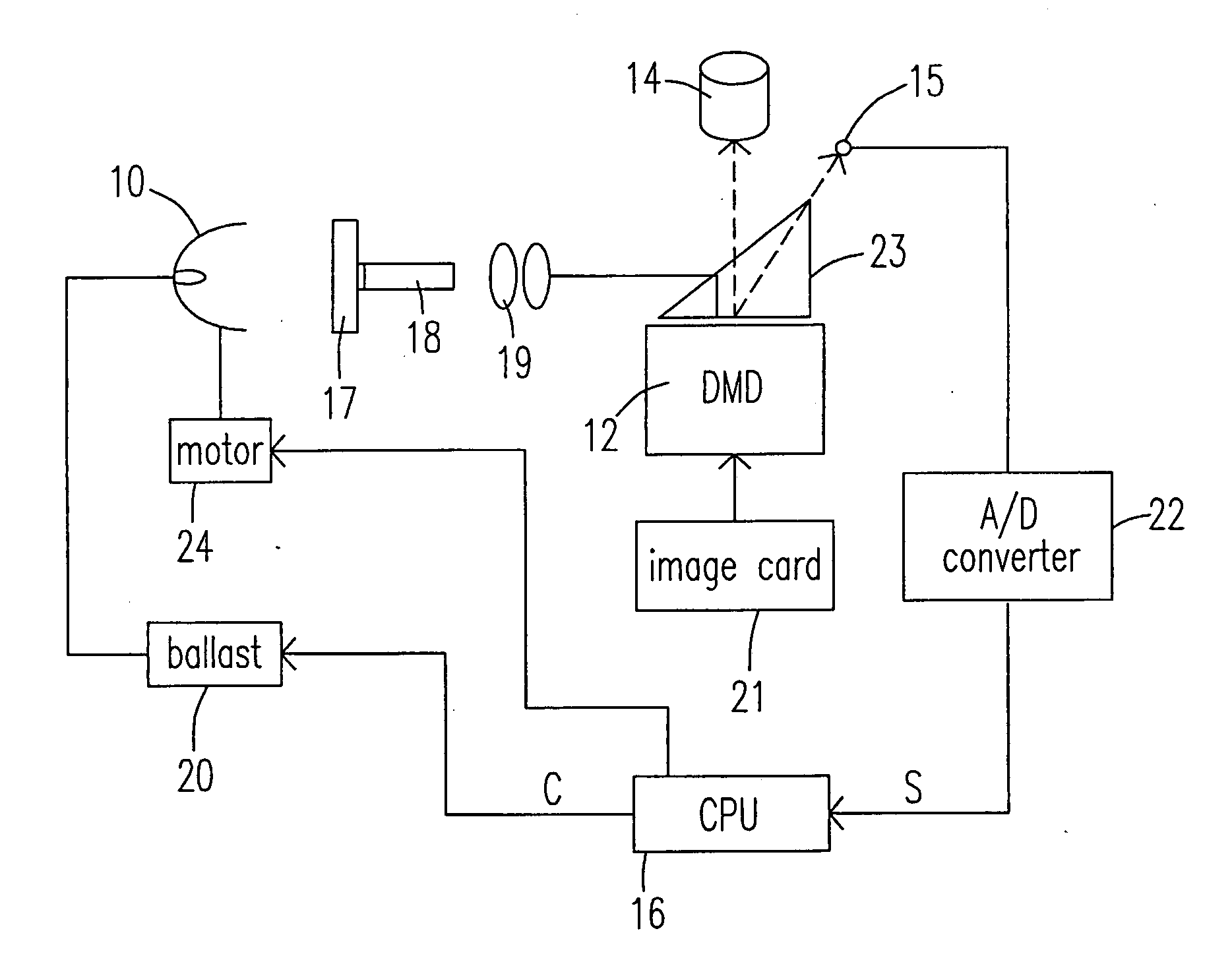
[0010] Preferably, the ballast is coupled with a motor to lower the brightness of the light source projected on the screen by using the motor to move the light source.
[0019] Preferably, the respective ballast is coupled with a respective motor to lower the brightness of the light source by using the motor to move the light source.

Problems solved by technology

Since the way of such adjustment is open-loop, the dynamic range of image is easily lost.
Besides, because the light source is unable to be adjusted when the image brightness is dimmed, the life of the light source is shortened.
However, such prior art is disadvantageous since the lumen out of the light source is high, therefore also shortening the life of the light source.

Method used


Image

  • Brightness-adjusting device for video wall system and method therefor
  • Brightness-adjusting device for video wall system and method therefor
  • Brightness-adjusting device for video wall system and method therefor

Examples


Embodiment Construction

[0033] The present invention will now be described more specifically with reference to the following embodiments. It is to be noted that the following descriptions of preferred embodiments of this invention are presented herein for purposes of illustration and description only; it is not intended to be exhaustive or to be limited to the precise form disclosed.

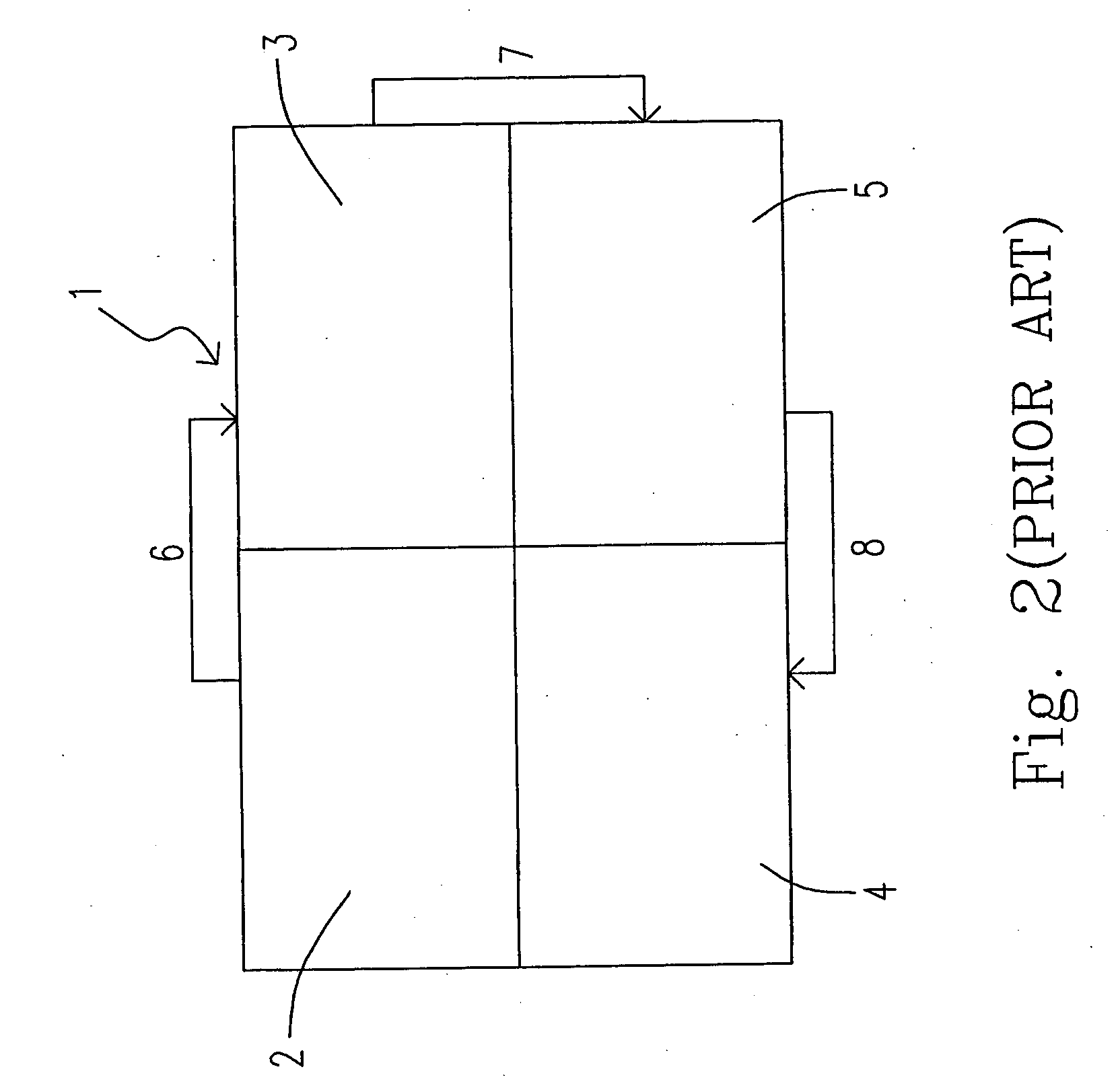
[0034] Please refer to FIG. 2, which is a schematic view showing the screen structure of a conventional video wall system. The video wall system includes a master screen 2 and three slave screens 3, 4 and 5, which are interconnected with each other via communication cables 6, 7 and 8 (e.g. RS232 or RS485 cables). The master screen coordinates the data transmitted from all slave screens to display the image. The brightness consistency among the respective screens on the video wall system is important. If the brightness of each screen is inconsistent, the total display effect of the video wall system is certainly inferior.

[0035...


PUM


Abstract

A brightness-adjusting device for a screen is provided. The brightness-adjusting device includes a light source providing an incident light required to project an image on the screen, a sensor disposed at a position so as to receive the incident light and obtain a digital brightness signal accordingly, and a processor electrically connected to the sensor, receiving the signal and determining a target brightness for adjusting a brightness of the light source accordingly.

Description

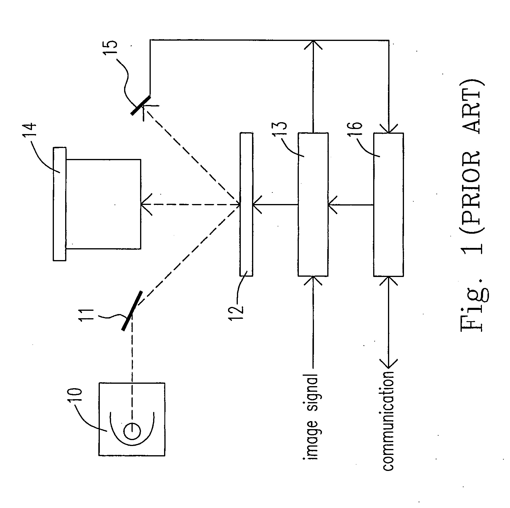
FIELD OF THE INVENTION [0001] The present invention relates to a brightness-adjusting device for a video wall system and the method therefor, in particular to a brightness-adjusting device for a video wall system and the method therefor by virtue of brightness adjustment of the light source to obtain substantially consistent screen brightness of the video wall system. BACKGROUND OF THE INVENTION [0002] Please refer to FIG. 1, which is a schematic diagram showing a conventional brightness-adjusting device for a video wall system. The brightness-adjusting device includes a light source 10, a mirror 11, a digital micro-mirror device (DMD) 12, a brightness correction portion 13, a projection lens 14 and a brightness sensor 15. In the brightness-adjusting device, the light source 10 irradiates light to the mirror 11 and the light is reflected to the DMD 12. When the DMD 12 is in on state, it displays an image to be projected in accordance with an image signal of the brightness correction...

Claims


Application Information

Patent Timeline
IPC IPC(8): H04N5/57
CPCH04N5/57H04N5/7458H04N9/3147H04N21/4122H04N21/4131H04N21/42202
Inventor WEN-CHIN, CHENG
Owner LUMENS DIGITAL OPTICS
Learn More