
Headphones for 3d sound

Inactive Publication Date: 2007-05-03
HILDEBRANDT JAMES G
View PDF12 Cites 45 Cited by
  • Summary
  • Abstract
  • Description
  • Claims
  • Application Information

AI Technical Summary

Benefits of technology

[0015] 3. The ability to overcome the restriction of having to place the headset speaker within a few millimeters of the ear and maintain the sound quality. This is done largely with the addition of a chamber on the rear of the speaker and is aided with the tube sound guide and the horn terminus. This technique improves the sound from any small speaker to the extent that it even makes it practical to use headset speakers as room speakers.
[0016] 4. No need for electronic hardware to process the electrical signals to create the timing, intensity, pinna effects, or head tracking effects. The placement of the speakers in the present invention creates the correct timing. Use of damping material in the tubes between the speakers creates the intensity drop as is normally heard for sounds originating to one side of the head with the higher frequencies damped more than the low frequencies.
[0017] 5. The ability to combine the advantages of the rear speaker chamber and tube sound guide with standard electronic methods to produce a compact headset and superior sound.

Problems solved by technology

Conventional headphones do not account for the effects of the human outer ear to produce realistic sounds and typically make no attempt to produce the sound cues needed to locate the direction of the sound.
These effects are difficult to reproduce in headsets, due to the limited space that is available for speaker placement, and the need for compact packaging.
Further, in conventional headphone design, if the speaker is not placed within a few millimeters of the ear, then the sound quality greatly diminishes.
There are four main methods that humans use, all of which are used in concert as no one method alone is adequate to pinpoint the source of the sound.
Furthermore, the time difference between the ears also creates a phase difference between the signals at each ear.
However, the methods can not adapt to every person and so are limited.

Method used


Image

  • Headphones for 3d sound
  • Headphones for 3d sound
  • Headphones for 3d sound

Examples


Embodiment Construction

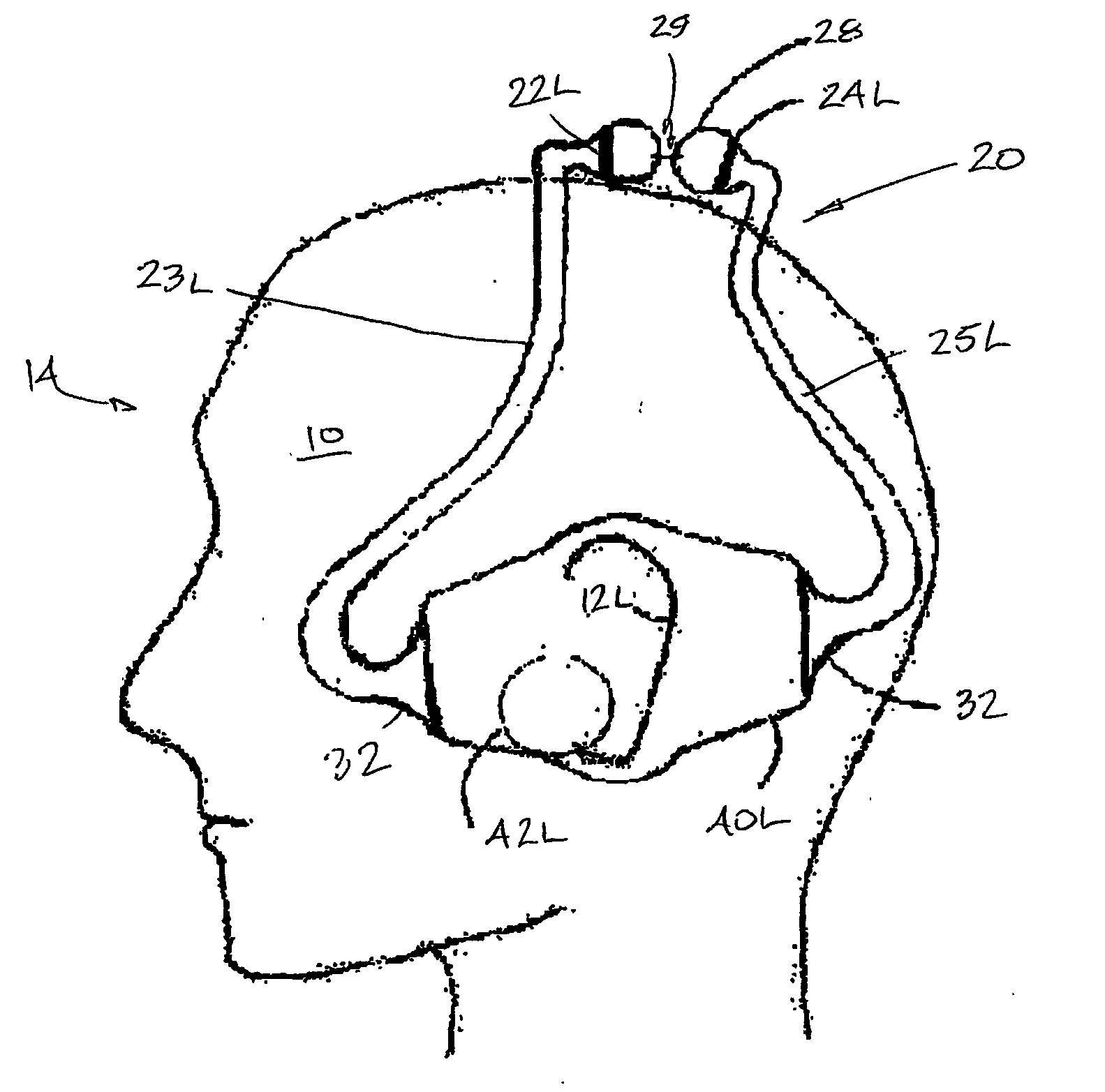
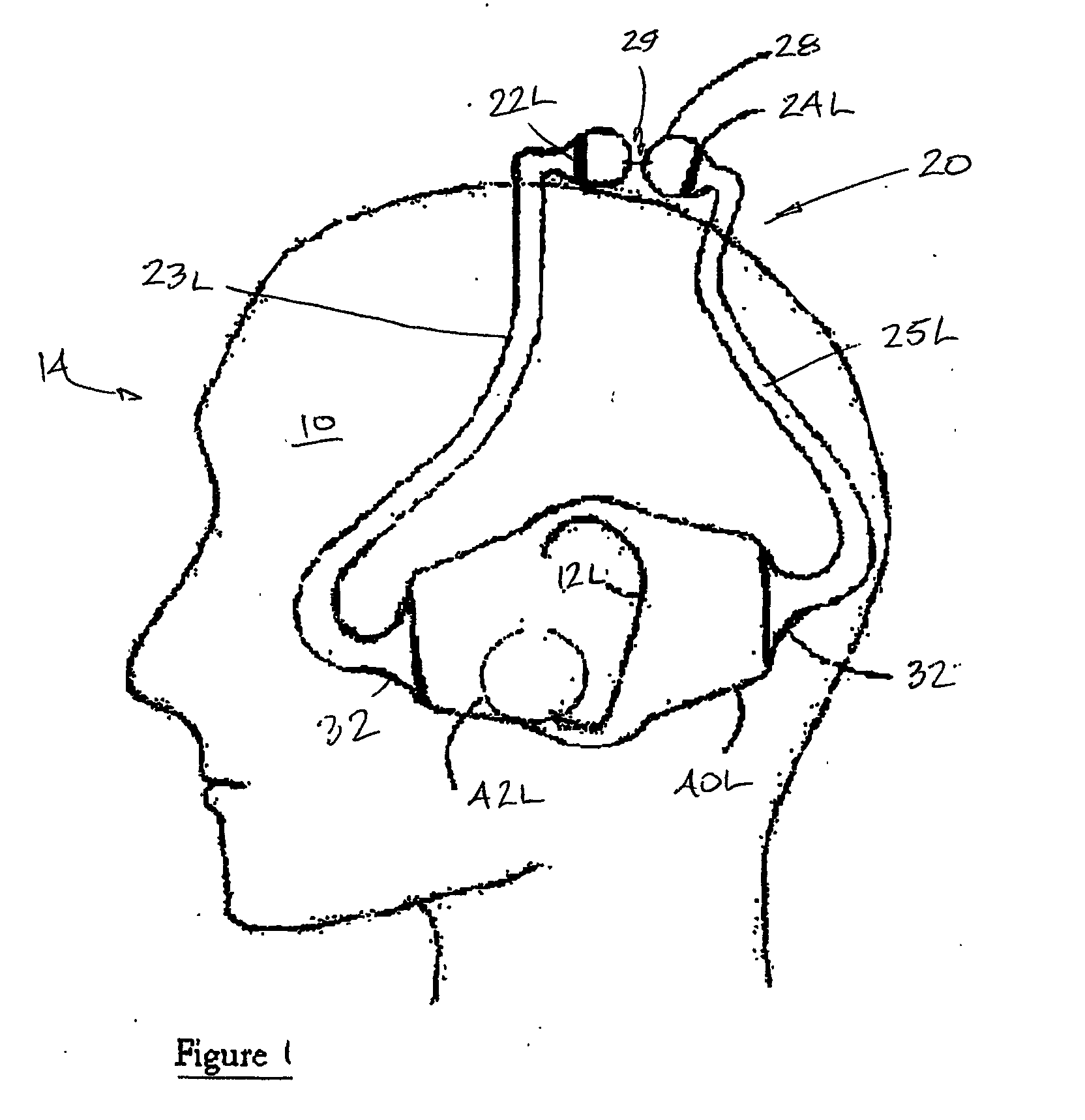
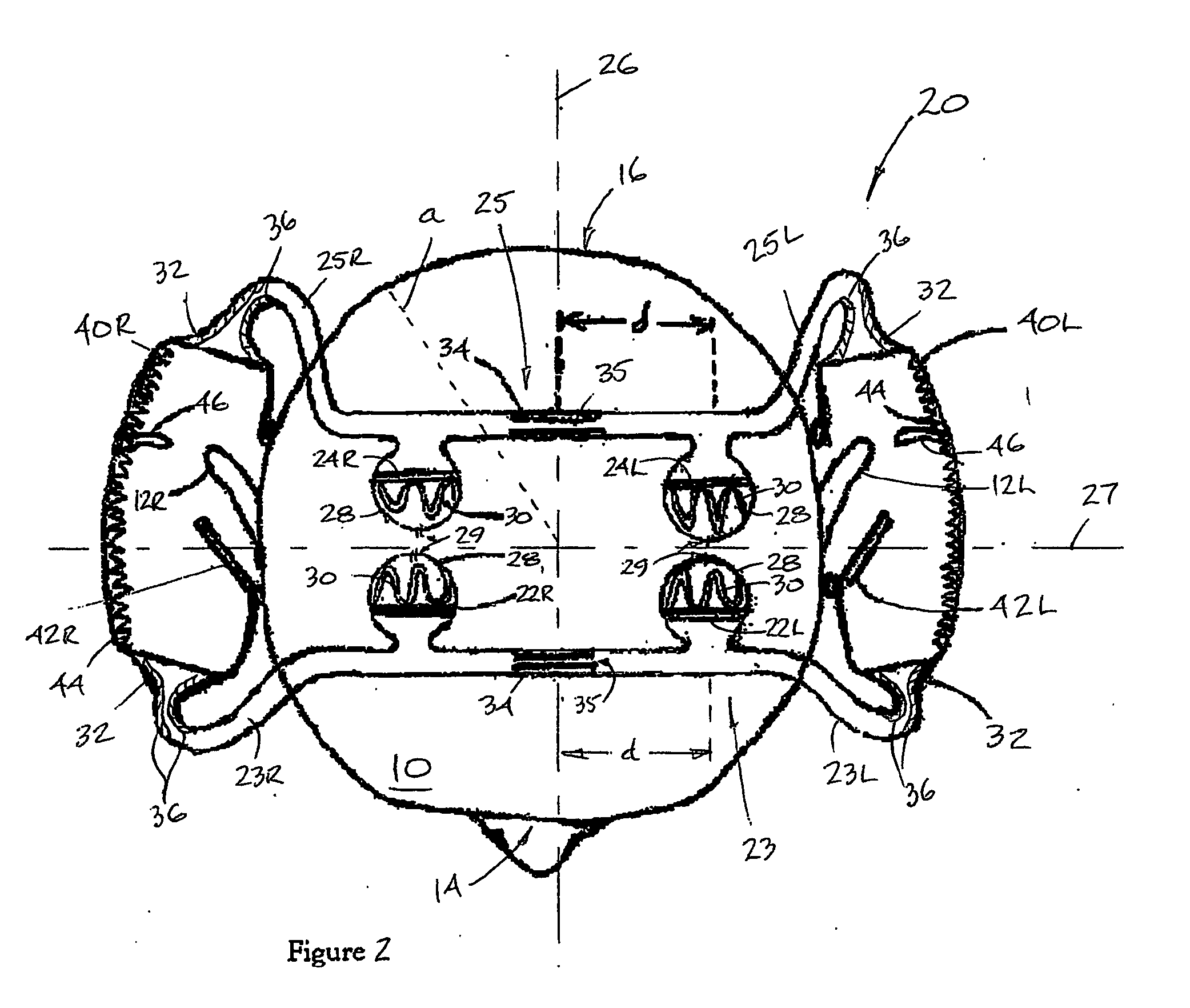
[0032] The present invention provides a headset apparatus suitable for providing a surround sound effect. The headset provides the user (also referred to herein as the “listener”) with the ability to locate the direction from which sounds are originating anywhere in 3D space, much like room speakers, and provides a dynamic quality of sound. After using the headsets described herein, users describe other headsets as sounding “dead’. The present invention also provides a reduced “in-the-head” fatigue that is commonly experienced with prior art headsets. When describing the present invention, all terms not defined herein have their common art-recognized meanings.

[0033] In the present invention speakers are placed in hollow tubes at preset locations to produce desired timing and intensity location cues. The sound from front speakers is emitted from the ends of the tubes in front of the user's ears, and so the pinna effect for frontal sounds is correctly reproduced for every user. No ma...


PUM


Abstract

Headsets (20, 50, 60, 71) provide surround sound and full 3 dimensional effects to a user to simulate the effects of direction and sound source. Advantages include: surround sound effect without the limitations of Head-Related Transfer Functions, and pinna effect customized to each user's ears; horn shape tube outlets (32) to create an efficient transmission of sound; ability to space the headset speakers (22, 24) away from the user's ear and to maintain sound quality by addition of a chamber (28) behind the speakers (22, 24), with the aid of tube sound guides (23, 25) and the horn shaped outlets; and, no need for electronic hardware to process the electrical signals to create desired effects as placement of the speakers creates the correct timing, and damping material (34) in the tubes between speakers creates a desired intensity drop. Head tracking capability is also provided.

Description

FIELD OF THE INVENTION [0001] The present invention relates to headphones generally, and in particular relates to headphones that provide surround sound effects to a user such that the effects of direction and sound source can be simulated. BACKGROUND OF THE INVENTION [0002] Conventional headphones do not account for the effects of the human outer ear to produce realistic sounds and typically make no attempt to produce the sound cues needed to locate the direction of the sound. In a theatre type application, the sound signals from surround sound are created to be played on speakers that are in specific locations in the room. For example, one signal is created to be played on a speaker that is in front of the listener and about 45 degrees to the left. Another is created to be played on a speaker that is about the same distance from the listener but behind the listener and at approximately 60 degrees from directly behind the listener. The angle and distance from the listener creates t...

Claims


Application Information

Patent Timeline
IPC IPC(8): H04R25/00H04R5/033
CPCH04R1/1075H04R5/0335H04R2205/022H04S1/005
Inventor HILDEBRANDT, JAMES G.
Owner HILDEBRANDT JAMES G
Learn More