
Method of routing I/O adapter error messages in a multi-host environment

Inactive Publication Date: 2007-05-03
LENOVO GLOBAL TECH INT LTD
View PDF56 Cites 48 Cited by
  • Summary
  • Abstract
  • Description
  • Claims
  • Application Information

AI Technical Summary

Benefits of technology

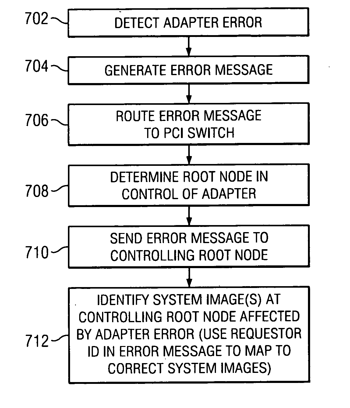
[0007] The invention is generally directed to a distributed computer system comprising multiple root nodes, and further comprising one or more PCI switches and one or more I/O adapters, wherein each root node includes one or more system images. In one useful embodiment, a method is provided for routing I/O error messages to a corresponding root node. The method includes the steps of detecting occurrence of an error at a specified one of the adapters, wherein the error affects one of the system images, and generating an error message at the s

Problems solved by technology

However, PCI-E currently does not permit the sharing of input / output (I / O) adapters in topologies where there are multiple hosts with multiple shared PCI buses.
Thus, such adapters cannot be shared between clustered blades, or even between multiple roots within a clustered system.
In an environment containing multiple blades or blade clusters, it can be very costly to dedicate a PCI adapter for use with only a single blade.
The inability to share these expensive adapters between blades has, in fact, contributed to the slow adoption rate of certain new network technologies such as 10 GigE.
Moreover, there is a constraint imposed by the limited space available in blades to accommodate I / O adapters.
Moreover, it is necessary to notify the system images in the respective root nodes that errors have occurred which may affect them.
In general, I / O adapter errors in a multi-root node environment can freeze the operations of systems using those adapters.

Method used


Image

  • Method of routing I/O adapter error messages in a multi-host environment
  • Method of routing I/O adapter error messages in a multi-host environment
  • Method of routing I/O adapter error messages in a multi-host environment

Examples


Embodiment Construction

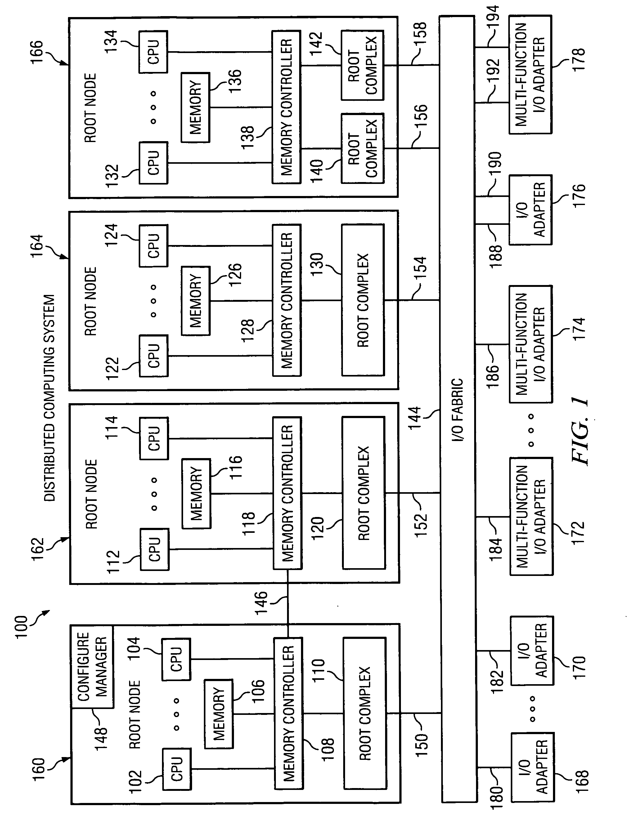
[0016]FIG. 1 shows a distributed computer system 100 comprising a preferred embodiment of the present invention. The distributed computer system 100 in FIG. 1 takes the form of multiple root complexes (RCs) 110, 120, 130, 140 and 142, respectively connected to an I / O switched-fabric bus 144 through I / O links 150, 152, 154, 156 and 158, and to the memory controllers 108, 118, 128 and 138 of the root nodes (RNs) 160-166. The I / O fabric is attached to I / O adapters (IOAs) 168-178 through links 180-194. The IOAs may be single function, such as IOAs 168-170 and 176, or multiple function, such as IOAs 172-174 and 178. Moreover, respective IOAs may be connected to the I / O fabric 144 via single links, such as links 180-186, or with multiple links for redundancy, such as links 188-194.

[0017] The RCs 110, 120, and 130 are integral components of RN 160, 162 and 164, respectively. There may be more than one RC in an RN, such as RCs 140 and 142 which are both integral components of RN 166. In ad...


PUM


Abstract

A method and apparatus is provided for routing error messages in a distributed computer system comprising multiple root nodes, and further comprising one or more PCI switches and one or more I / O adapters, wherein each root node includes one or more system images. In one useful embodiment, a method is provided for routing I / O error messages to root nodes respectively associated with the errors contained in the messages. The method includes detecting occurrence of an error at a specified one of the adapters, wherein the error affects one of the system images, and generating an error message at the specified adapter. The method further comprises routing the error message from the specified adapter to the particular root node that includes the affected system image. The error message is then selectively processed at the particular root node, in order to identify the affected system image. Usefully, the step of routing the error message includes using a bus / device / function number associated with the error, together with a routing table located in one of the PCI switches, to route the error message to the correct root node and system image.

Description

BACKGROUND OF THE INVENTION [0001] 1. Field of the Invention [0002] The invention disclosed and claimed herein generally pertains to a method and related apparatus for routing PCI transaction packets between multiple root nodes and adapters, through a PCI switched-fabric bus. More particularly, the invention pertains to a method of the above type wherein packets from different system images of the root nodes may be routed through the fabric to share the same adapter. Even more particularly, the invention pertains to a method of the above type wherein it is necessary to provide an arrangement for routing an error notification message from an adapter to a system image affected by the error. [0003] 2. Description of the Related Art [0004] As is well known by those of skill in the art, PCI Express (PCI-E) is widely used in computer systems to interconnect host units to adapters or other components, by means of a PCI switched-fabric bus or the like. However, PCI-E currently does not perm...

Claims


Application Information

Patent Timeline
IPC IPC(8): H04J3/14
CPCG06F11/0712G06F11/0724G06F11/0775G06F11/0784
Inventor BOYD, WILLIAM T.FREIMUTH, DOUGLAS M.HOLLAND, WILLIAM G.HUNTER, STEVEN W.RECIO, RENATO J.THURBER, STEVEN M.VEGA, MADELINE
Owner LENOVO GLOBAL TECH INT LTD
Learn More