Crank axle drive structure for bicycle

a crank axle and drive structure technology, applied in the direction of mechanical control devices, process and machine control, instruments, etc., can solve the problems of reducing the speed of the bicycle, reducing the rotation speed of the chainwheel, and limited specification of the conventional chainwheel, so as to simplify the construction and shorten the diameter of the chainwheel , the effect of efficient shortening of the specification of the chainwheel

Inactive Publication Date: 2007-04-26
LAI CHIN CHOU +1
View PDF8 Cites 1 Cited by
  • Summary
  • Abstract
  • Description
  • Claims
  • Application Information

AI Technical Summary

Benefits of technology

[0006] The primary objective of the present invention is to provide a crank axle drive structure, wherein the diameter of the chainwheel is shortened without reducing the rotation speed of the chainwheel.
[0007] Another objective of the present invention is to provide a crank axle drive structure, wherein the specification of the chainwheel is shortened efficiently, so that the crank axle drive structure has a simplified construction, thereby decreasing costs of fabrication.
[0008] A further objective of the present invention is to provide a crank axle drive structure, wherein the chainwheel has a smaller size, so that the force applied on the crank axle is reduced, thereby saving the manual work.
[0009] A further objective of the present invention is to provide a crank axle drive structure, wherein the chainwheel has a smaller size and a lighter weight, so that the crank axle drive structure has a smaller volume, thereby facilitating package, storage and transportation of the crank axle drive structure.
[0010] A further objective of the present invention is to provide a crank axle drive structure, wherein the inner teeth of the bottom bracket have a tooth number greater than that of the outer teeth of the chainwheel fixing seat, so that the rotation speed of the chainwheel fixing seat is increased, thereby shortening the diameter of the chainwheel so as to perform a pedaling action at the higher rotation speed in an energy saving manner.

Problems solved by technology

However, when the diameter of the chainwheel is shortened, the rotation speed of the chainwheel is reduced, thereby reducing the speed of the bicycle.
Thus, the specification of the conventional chainwheel is limited.

Method used


Image

  • Crank axle drive structure for bicycle
  • Crank axle drive structure for bicycle
  • Crank axle drive structure for bicycle

Examples


Embodiment Construction

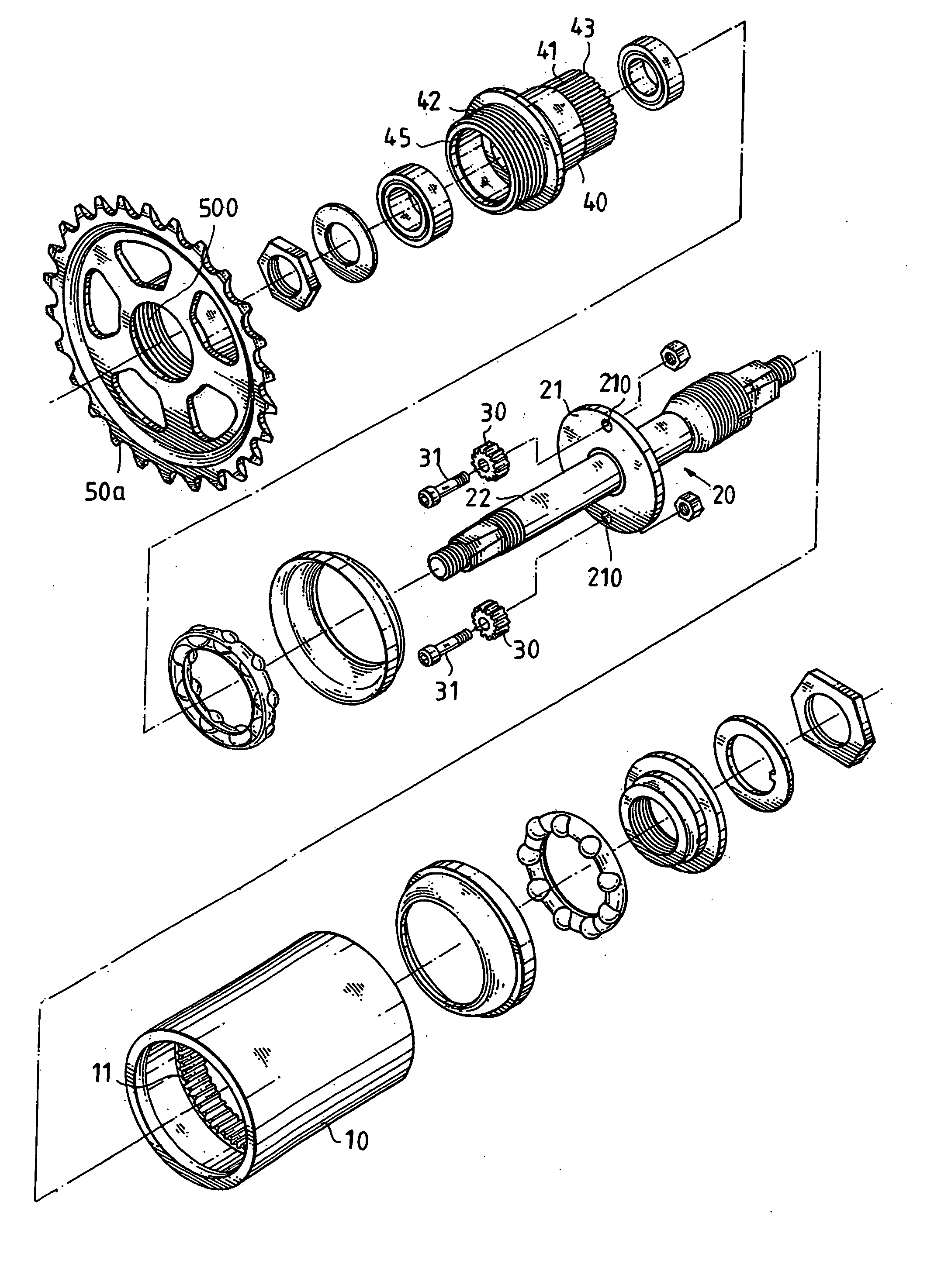
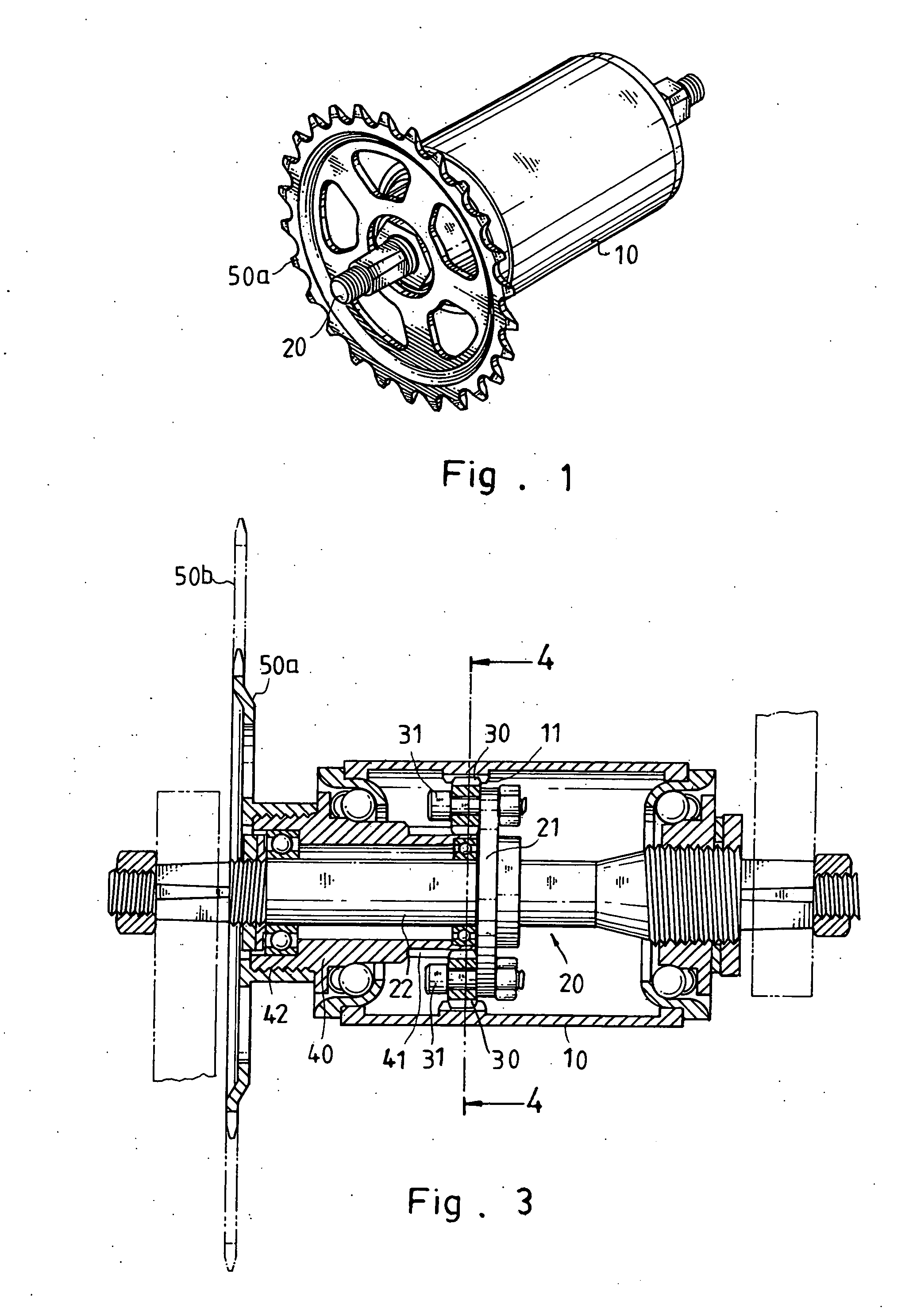
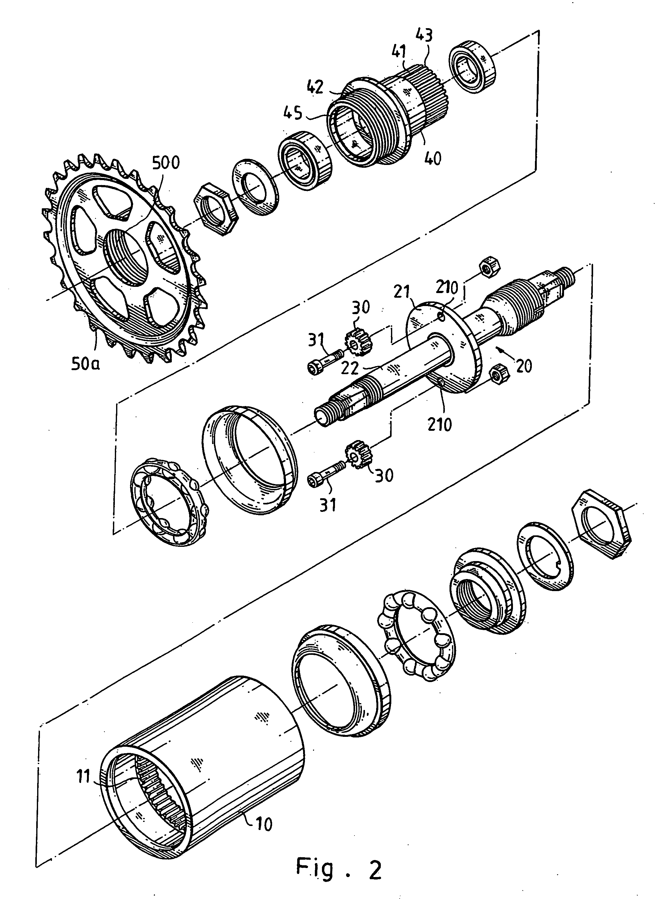
[0016] Referring to the drawings and initially to FIGS. 1-3, a crank axle drive structure for a bicycle in accordance with the preferred embodiment of the present invention comprises a bottom bracket 10 having an inner wall provided with a plurality of inner teeth 11, a crank axle 20 rotatably mounted in the bottom bracket 10, at least one drive gear 30 rotatably mounted on the crank axle 20 and meshing with the inner teeth 11 of the bottom bracket 10, a chainwheel fixing seat 40 rotatably mounted on the crank axle 20 and provided with a plurality of outer teeth 41 meshing with the drive gear 30, and a chainwheel 50a secured to the chainwheel fixing seat 40 to rotate therewith. In the preferred embodiment of the present invention, the crank axle drive structure comprises two opposite drive gears 30 rotatably mounted on the crank axle 20 and arranged in a symmetric manner.

[0017] The inner teeth 11 of the bottom bracket 10 are arranged in the bottom bracket 10 in an annular manner.

[...


PUM


Abstract

A crank axle drive structure for a bicycle includes a bottom bracket having inner teeth, a crank axle rotatably mounted in the bottom bracket, at least one drive gear rotatably mounted on the crank axle and meshing with the inner teeth, and a chainwheel fixing seat rotatably mounted on the crank axle and provided with outer teeth meshing with the drive gear. Thus, the inner teeth of the bottom bracket have a tooth number greater than that of the outer teeth of the chainwheel fixing seat, so that the rotation speed of the chainwheel fixing seat is increased, thereby shortening the diameter of the chainwheel so as to perform a pedaling action at the higher rotation speed in an energy saving manner.

Description

BACKGROUND OF THE INVENTION [0001] 1. Field of the Invention [0002] The present invention relates to a crank axle drive structure, and more particularly to a crank axle drive structure for a bicycle. [0003] 2. Description of the Related Art [0004] A crank axle of a bicycle has an end provided with a chainwheel, a chain and a flywheel. Thus, when the crank axle is rotated, the chainwheel, the chain and the flywheel are driven by the crank axle drives to rotate in concert with the crank axle. The chainwheel has a tooth number greater than that of the flywheel. When the diameter of the chainwheel is shortened, the rider can apply a smaller force on the chainwheel, thereby saving the manual work. However, when the diameter of the chainwheel is shortened, the rotation speed of the chainwheel is reduced, thereby reducing the speed of the bicycle. Thus, the specification of the conventional chainwheel is limited. SUMMARY OF THE INVENTION [0005] In accordance with the present invention, the...

Claims


Application Information

Patent Timeline
Patent Type & Authority Applications(United States)
IPC IPC(8): G05G1/14G05G1/30
CPCY10T74/2164B62M11/145
Inventor LAI, CHIN-CHOUHUANG, BILL
Owner LAI CHIN CHOU
Why Eureka
Try Eureka