Communication system and method, and distributed control system and method
a communication system and control system technology, applied in the field of bidirectional communication, can solve the problems of unreasonably extended communication time and increased costs of data transmission for baud rate adjustment, and achieve the effect of reducing costs and high-quality communication
- Summary
- Abstract
- Description
- Claims
- Application Information
AI Technical Summary
Benefits of technology
Problems solved by technology
Method used
Image
Examples
first embodiment
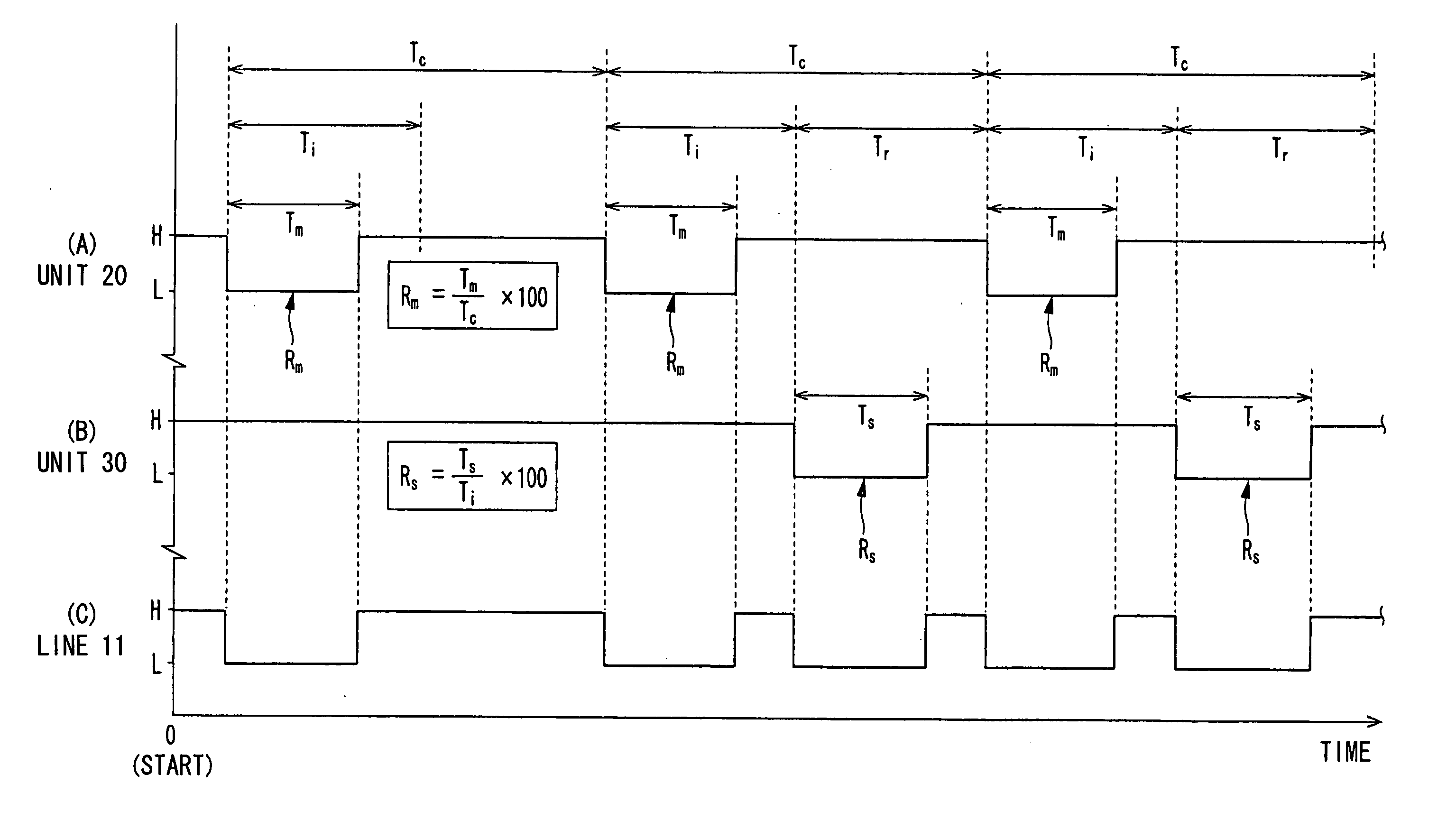
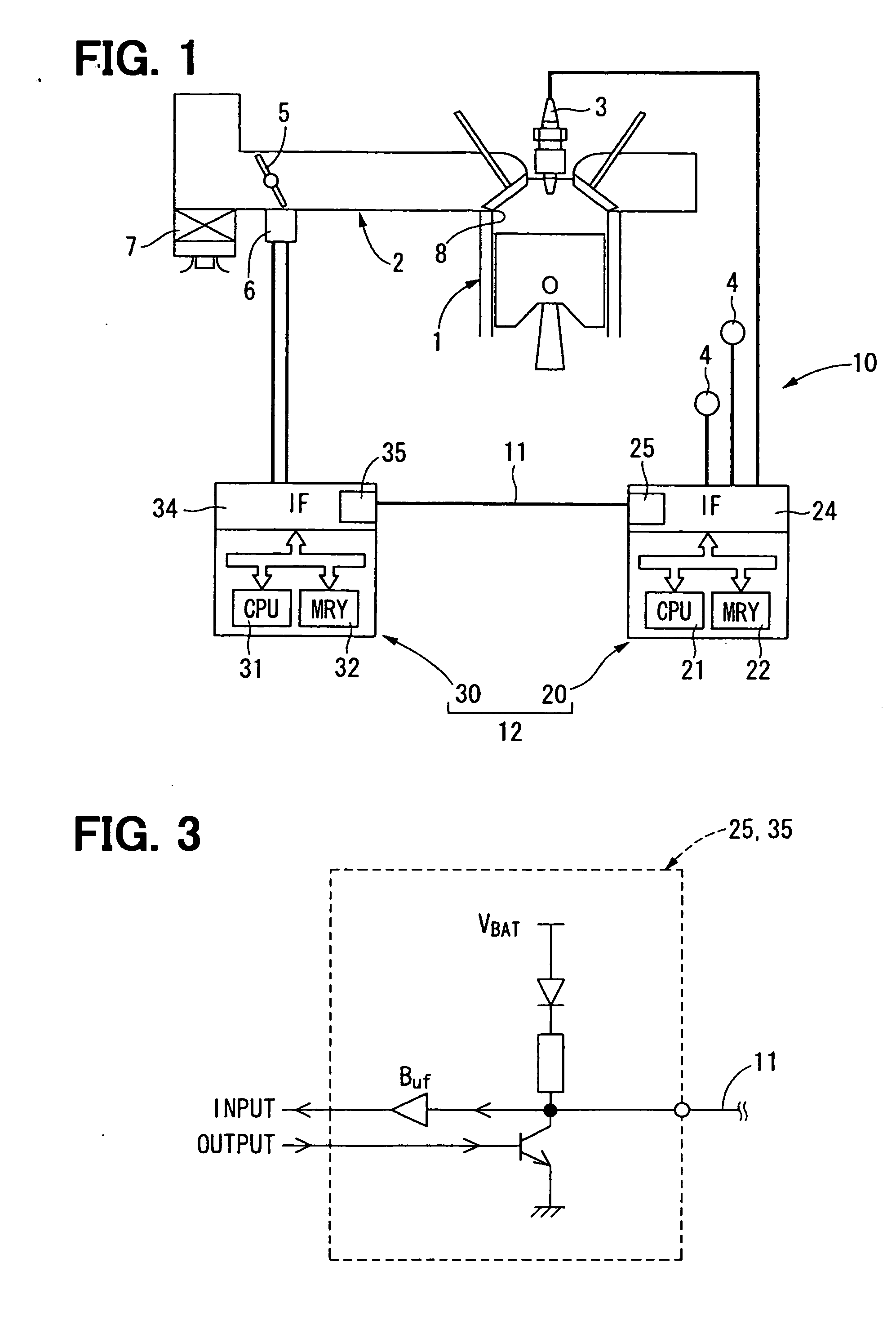
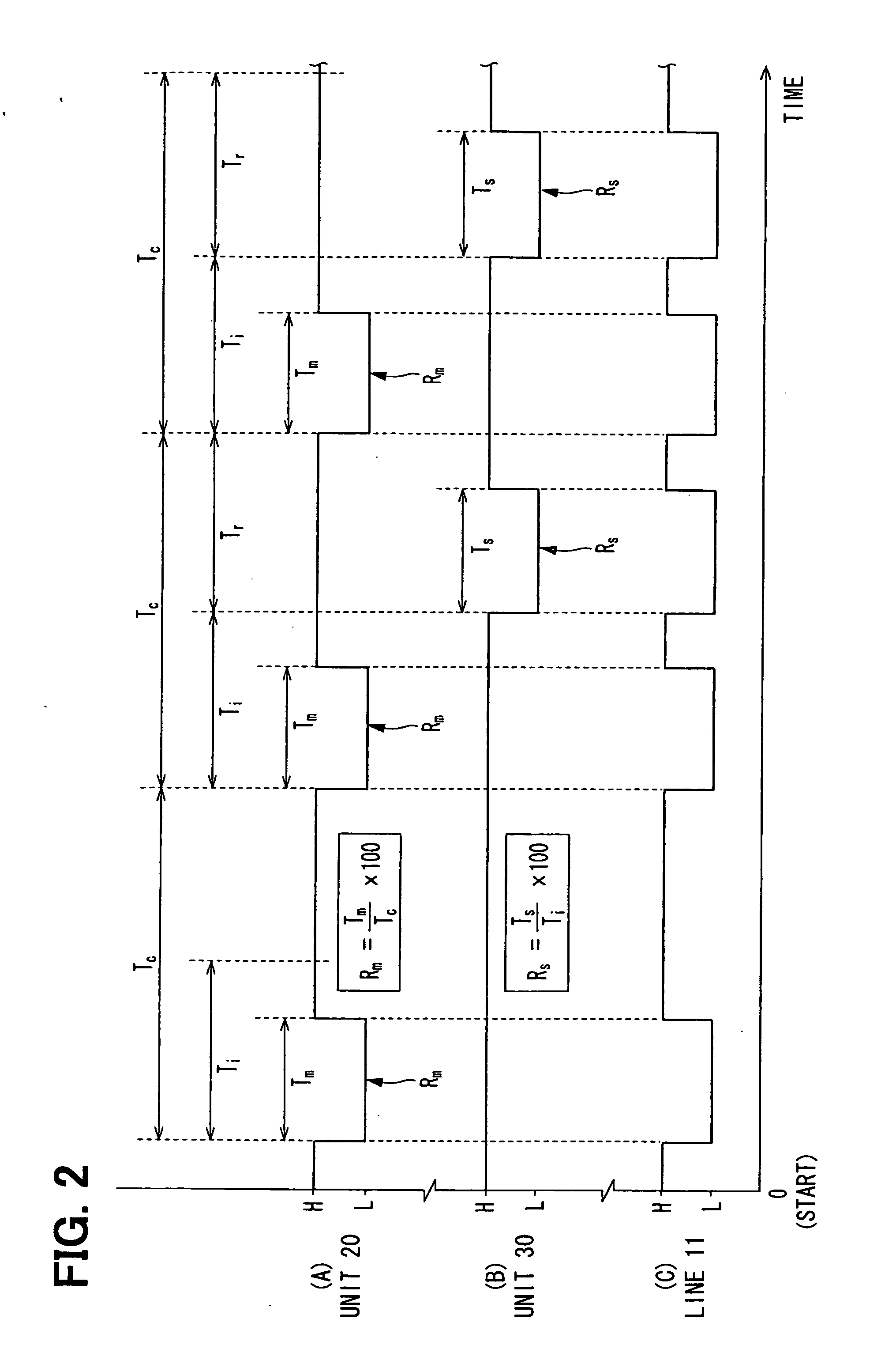
[0033] Referring first to FIG. 1, a distributed control system 10 is mainly constructed with a communication system 12 that mutually connects an engine control unit 20 and an intake control unit 30 through one signal line 11 such as a cable or a wiring harness. The control system thus distributedly control targets (engine and intake system) 1 and 2 connected to the control units 20 and 30, respectively.
[0034] In the communication system 12, the control units 20 and 30 are constructed with electric circuits such as microcomputers that respectively include CPUs 21 and 31, memories 22 and 32, and input / output interfaces (IF) 24 and 34. The input / output IFs 24 and 34 of the control units 20 and 30 respectively include IF circuits 25 and 35 for LIN as shown in FIG. 3 as IF circuits to which a signal line 11 is connected for communication between the units 20 and 30. Therefore, for data transmission between the control units 20 and 30 through a communication path formed by the signal lin...
second embodiment
[0053] As shown in FIG. 6, a distributed control system 100 of the second embodiment is mainly constructed with a communication system 102 that combines one engine control unit 120 as a master station and two intake control units 130 and 140 as slave stations. In this communication system 102, the control units 120, 130 and 140 are connected to a common bus 110 comprising one cable 110 via individual signal lines 112, 113 and 114. Thus, the communication system 102 forms a communication network of the bus type.
[0054] In the communication system 102, the control units 120, 130 and 140, like the first embodiment are constructed with electric circuits such as microcomputers that include CPUs 121, 131 and 141, memories 122, 132 and 142, and input / output IFs 124, 134 and 144. Like the first embodiment, the input / output IFs 124, 134 and 144 are provided with IF circuits 125, 135 and 145 for LIN, to which the above signal lines 112, 113 and 114 are connected respectively. Therefore, for d...
third embodiment
[0080] As shown in FIG. 10, in a communication system 202 of a distributed control system 200 according to the third embodiment, a drive unit 156 of an intake flow control valve 152 provided in an intake system 250 is connected to an input / output IF 34 of an intake control unit 210. The construction of the intake flow control valve 152 and the drive unit 156 is substantially the same as that in the second embodiment. Accordingly, the intake control unit 210 executes a program stored in the memory 212 by the CPU 31 to feed a drive signal based on a target opening degree of the intake control unit 210 to the drive unit 156, and receive a signal representative of an actual opening degree of the intake flow control valve 152 from the drive unit 156.
[0081] In the communication system 202, the engine control unit 220 has a construction similar to the engine control unit 20 of the first embodiment, except a program stored in the memory 222.
[0082] In the communication system 202, the cont...
PUM
 Abstract
Description
Claims
Application Information
 - R&D
- Intellectual Property
- Life Sciences
- Materials
- Tech Scout
- Unparalleled Data Quality
- Higher Quality Content
- 60% Fewer Hallucinations
Browse by: Latest US Patents, China's latest patents, Technical Efficacy Thesaurus, Application Domain, Technology Topic, Popular Technical Reports.
© 2025 PatSnap. All rights reserved.Legal|Privacy policy|Modern Slavery Act Transparency Statement|Sitemap|About US| Contact US: help@patsnap.com


