
Transflective type liquid crystal display device having high transmission and wide viewing angle characteristics

Inactive Publication Date: 2007-04-19
BOE HYDIS TECH
View PDF4 Cites 11 Cited by
  • Summary
  • Abstract
  • Description
  • Claims
  • Application Information

AI Technical Summary

Benefits of technology

[0013] Accordingly, the present invention has been made to solve the above-mentioned problems occurring in the prior art, and an object of the present invention is to provide a transflective type LCD device capable of improving the viewing angle characteristic even if a polarizing plate is accommodated in an array substrate.

Problems solved by technology

However, such a backlight unit may increase power consumption of the transmissive LCD device.
However, the reflective LCD device cannot be used in dark places.
However, according to the conventional transflective type LCD device, the lower polarizing plate is coated on the lower glass substrate of the array substrate, so that it is difficult to attach the retardation film to the inner portion of the lower glass substrate.

Method used


Image

  • Transflective type liquid crystal display device having high transmission and wide viewing angle characteristics
  • Transflective type liquid crystal display device having high transmission and wide viewing angle characteristics
  • Transflective type liquid crystal display device having high transmission and wide viewing angle characteristics

Examples


Embodiment Construction

[0040] Hereinafter, preferred embodiments of the present invention will be described with reference to accompanying drawings.

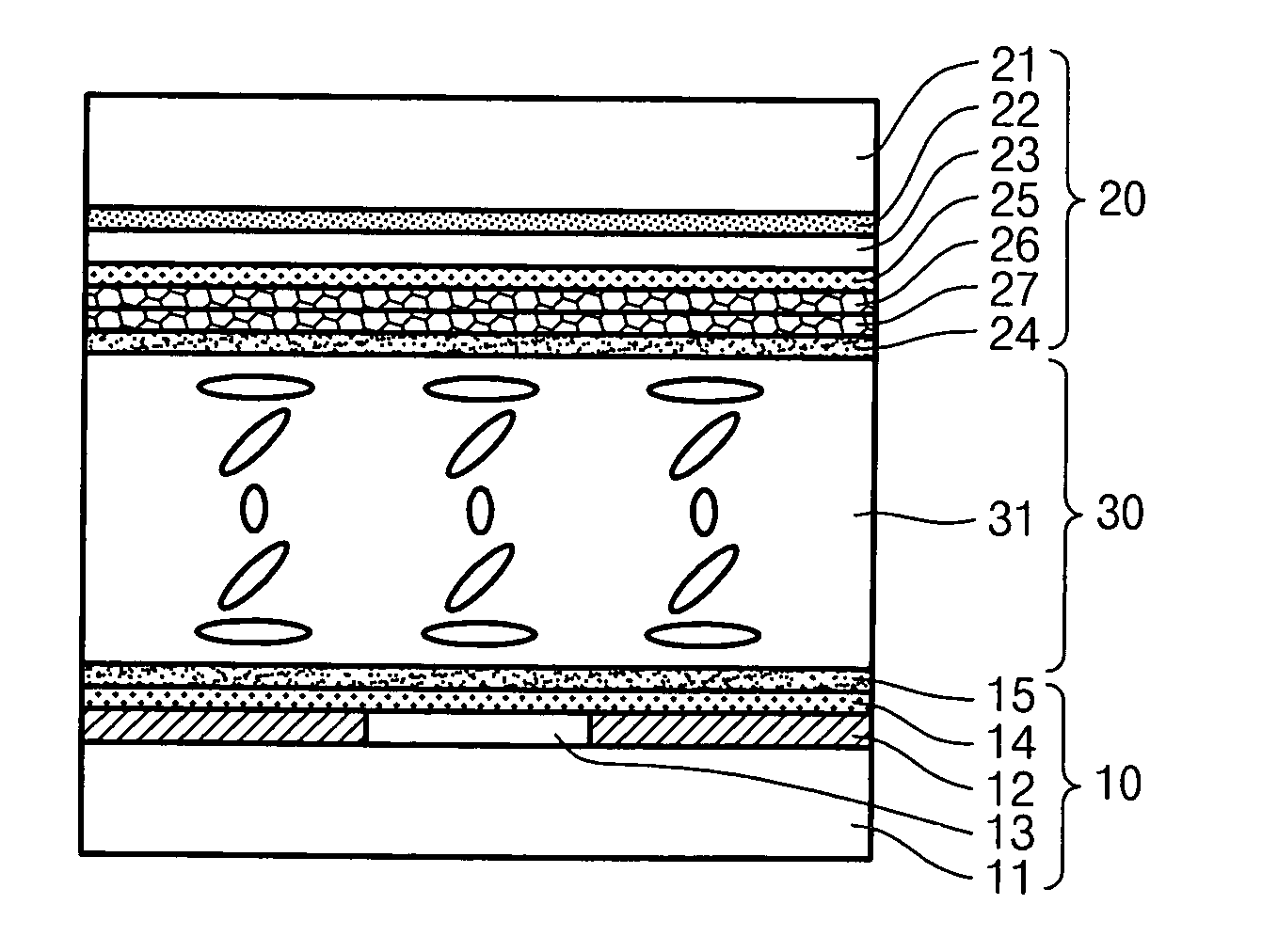
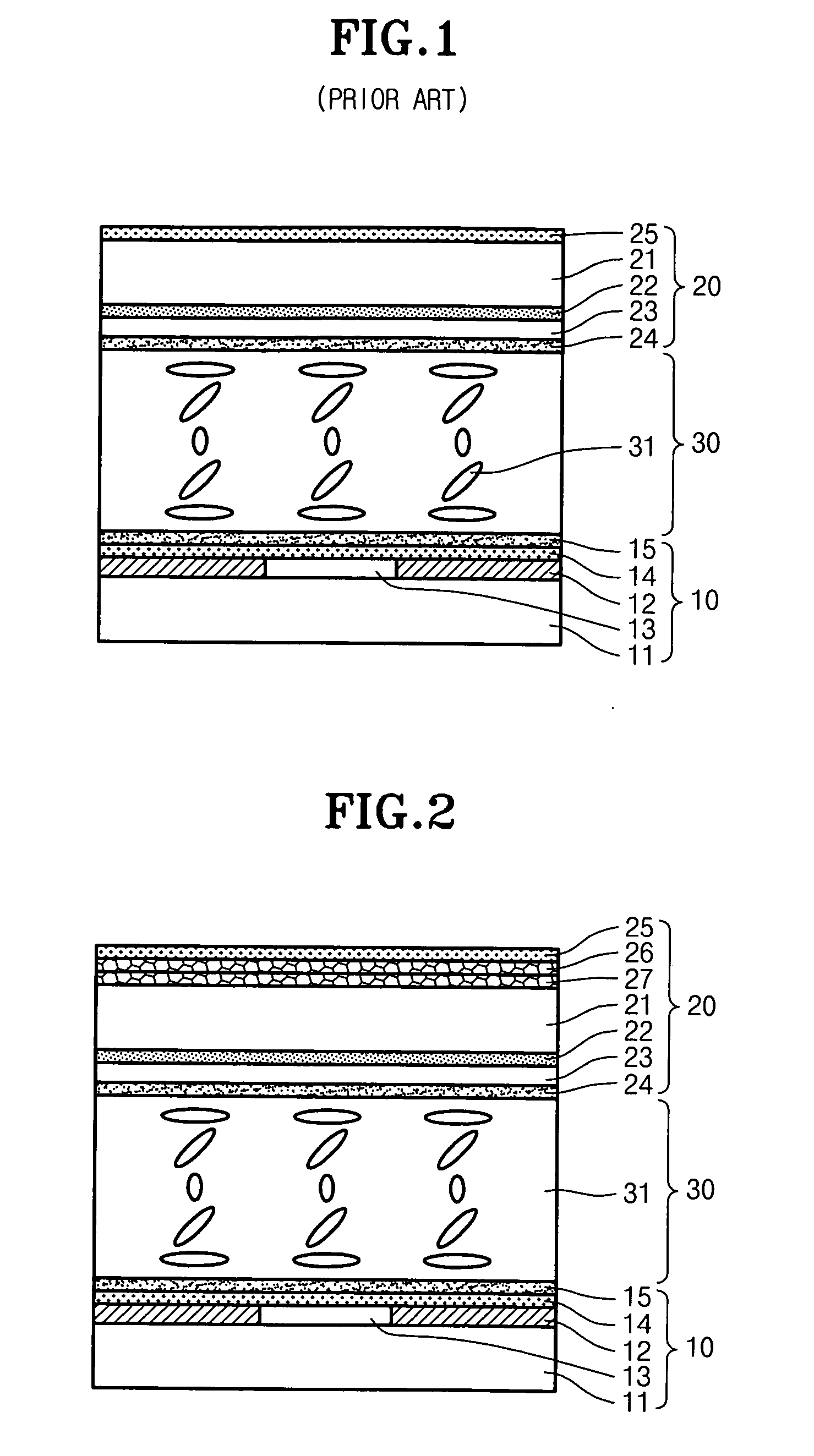
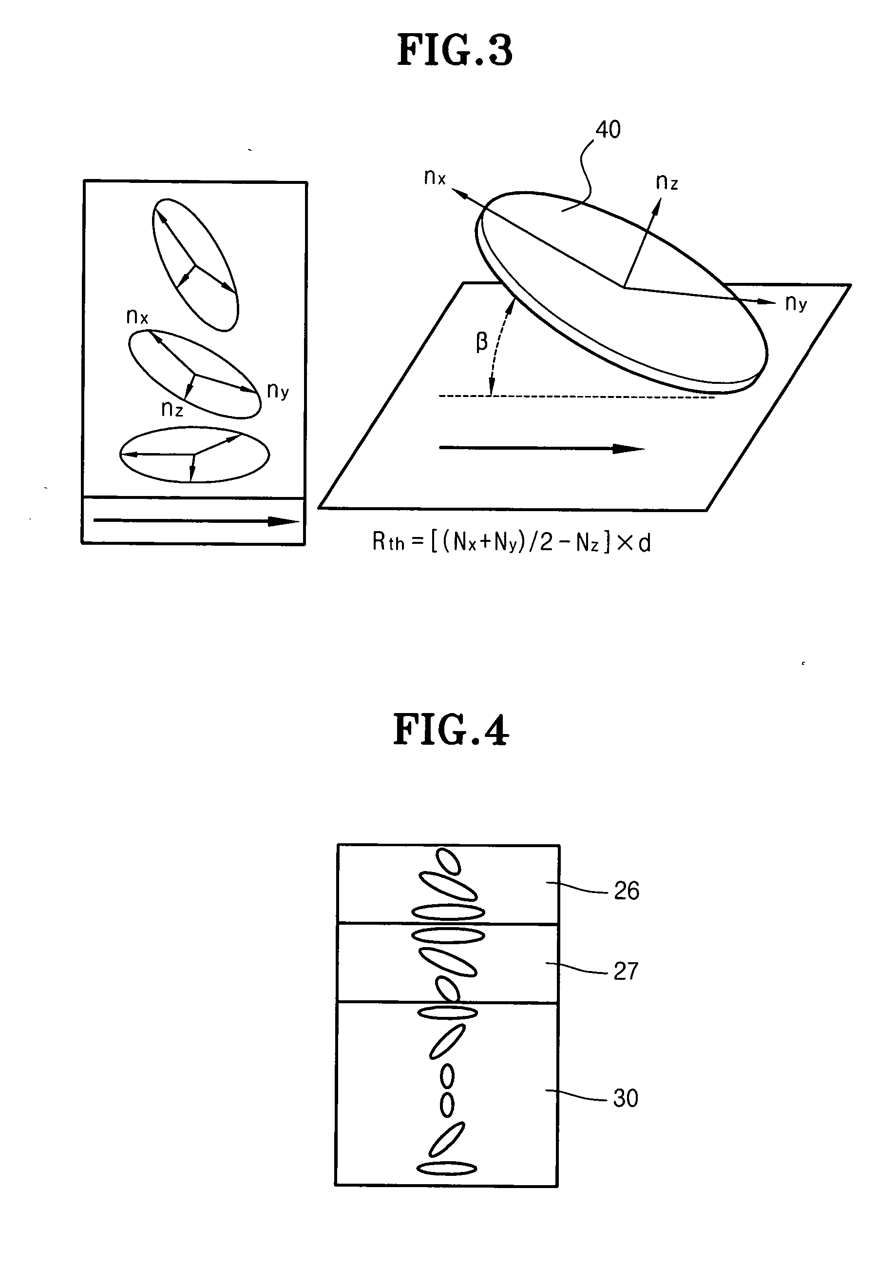
[0041] First, the technical principle of the present invention will be briefly explained. According to the present invention, when a lower polarizing plate is accommodated in an array substrate, two retardation films using disc-shaped liquid crystal molecules are aligned below an upper polarizing plate of a color filter substrate in such a manner that optical transmission axes of two retardation films cross each other at an angle of 90±3°. Herein, the optical transmission axes of two retardation films are obtained by averaging optical transmission axes of liquid crystal molecules provided in the retardation films.

[0042] In this case, the light compensation can be achieved not only along one direction, but also in a direction perpendicular to the one direction. Thus, it is possible to improve viewing angle characteristics of a transflective liquid crystal dis...


PUM


Abstract

Disclosed is a transflective type LCD device having high transmission and wide viewing angle characteristics. The transflective type LCD device includes first and second substrates aligned in opposition to each other, reflecting and transparent electrodes formed on one surface of the first substrate, a lower polarizing plate formed on the above electrodes, a lower alignment layer aligned on the lower polarizing plate, a color filter formed on one surface of the second substrate, a transparent common electrode formed on the color filter, an upper alignment layer formed on the transparent common electrode, two retardation films sequentially attached to an outer portion of the second substrate, an upper polarizing plate attached to the retardation films, and a liquid crystal layer including a plurality of liquid crystal molecules interposed between the first and second substrates.

Description

BACKGROUND OF THE INVENTION [0001] 1. Field of the Invention [0002] The present invention relates to a transflective type liquid crystal display (LCD) device. More particularly, the present invention relates to a transflective type LCD device having high transmission and wide viewing angle characteristics. [0003] 2. Description of the Prior Art [0004] As generally known in the art, LCD devices are classified into transmissive LCD devices using backlight units as light sources thereof and reflective LCD devices using natural light as light sources thereof. Since the transmissive LCD device employs the backlight unit to generate light, it can display bright images in dark places. However, such a backlight unit may increase power consumption of the transmissive LCD device. In contrast, the reflective LCD uses natural light as a light source without employing the backlight unit, so it can display images with low power consumption. However, the reflective LCD device cannot be used in dar...

Claims


Application Information

Patent Timeline
IPC IPC(8): G02F1/1335
CPCG02F1/133632G02F2001/133531G02F1/133531G02F1/1335
Inventor KIM, WAN CHEOLSUH, DONG HAEPARK, YOUNG IL
Owner BOE HYDIS TECH
Learn More