
Galvanic isolation of a signal using capacitive coupling embeded within a circuit board

a capacitive coupling and circuit board technology, applied in the direction of electrical apparatus construction details, diagnostic recording/measuring, printed circuit non-printed electric components association, etc., can solve the problems of affecting the use of the device, affecting the safety of users, etc., to achieve substantial galvanic isolation and low cost

Inactive Publication Date: 2007-04-12
WELCH ALLYN INC
View PDF22 Cites 36 Cited by
  • Summary
  • Abstract
  • Description
  • Claims
  • Application Information

AI Technical Summary

Benefits of technology

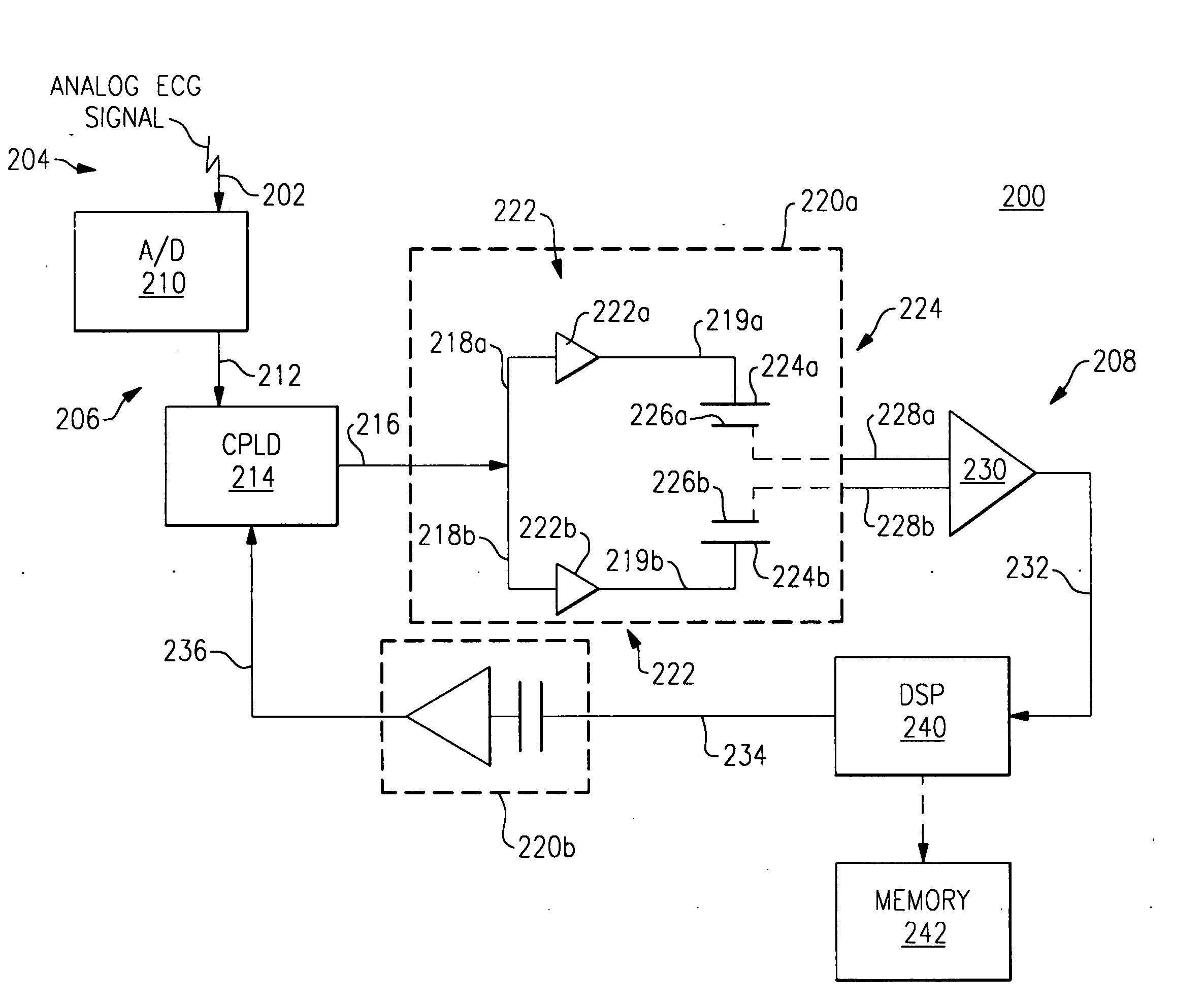
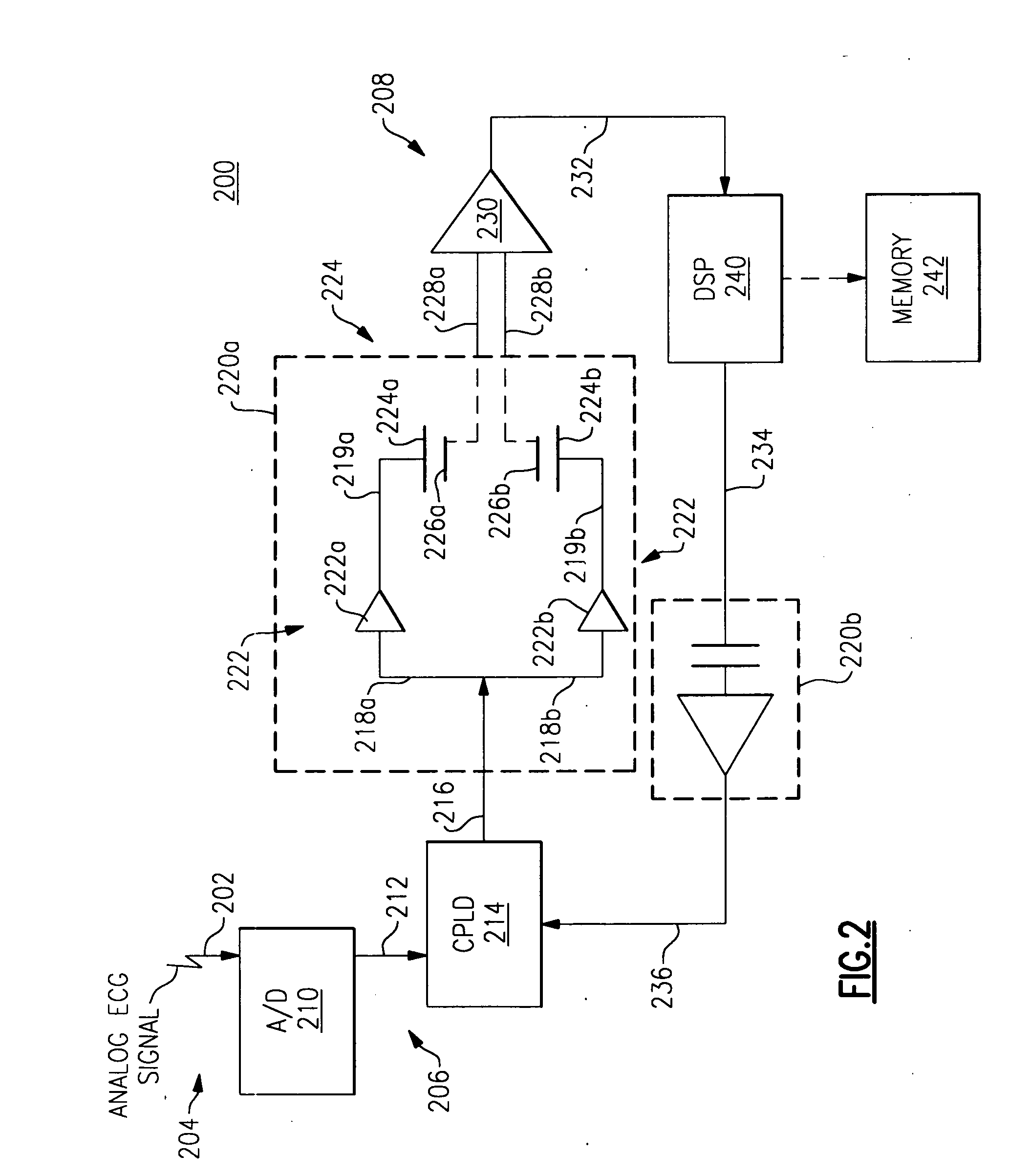
[0006] The invention provides galvanic isolation for signal communication between two electrical circuits via a capacitive coupler that is constructed from conductive and non-conductive layers of a printed circuit board. The invention can provide at low cost and with substantial galvanic isolation, the communication of data at rates of greater than 1 megabit per second. The galvanic isolation provided by the invention protects against common mode fields as well as limited differential mode fields. The invention makes use of pre-existing layers of a circuit board and does not require many other or expensive electrical components.

Problems solved by technology

As a result, there is a risk of unwanted transfer of electrical energy and signal interference between such devices and such objects while providing health care to a patient.
In some circumstances, the person may be experiencing some sort of cardiovascular instability, such as ventricular fibrillation.
The defibrillation shock can create a voltage surge that can unintentionally conduct (travel) through one or more of the ECG contact electrodes and / or lead wires and cause interference with the communication of data between the ECG electrode and components of the ECG monitoring apparatus that process the ECG signals.
Further, the defibrillation shock not only interferes with the communication of data, but if not galvanically isolated, the defibrillation shock could also travel through the device and harm the user.

Method used


Image

  • Galvanic isolation of a signal using capacitive coupling embeded within a circuit board
  • Galvanic isolation of a signal using capacitive coupling embeded within a circuit board
  • Galvanic isolation of a signal using capacitive coupling embeded within a circuit board

Examples


Embodiment Construction

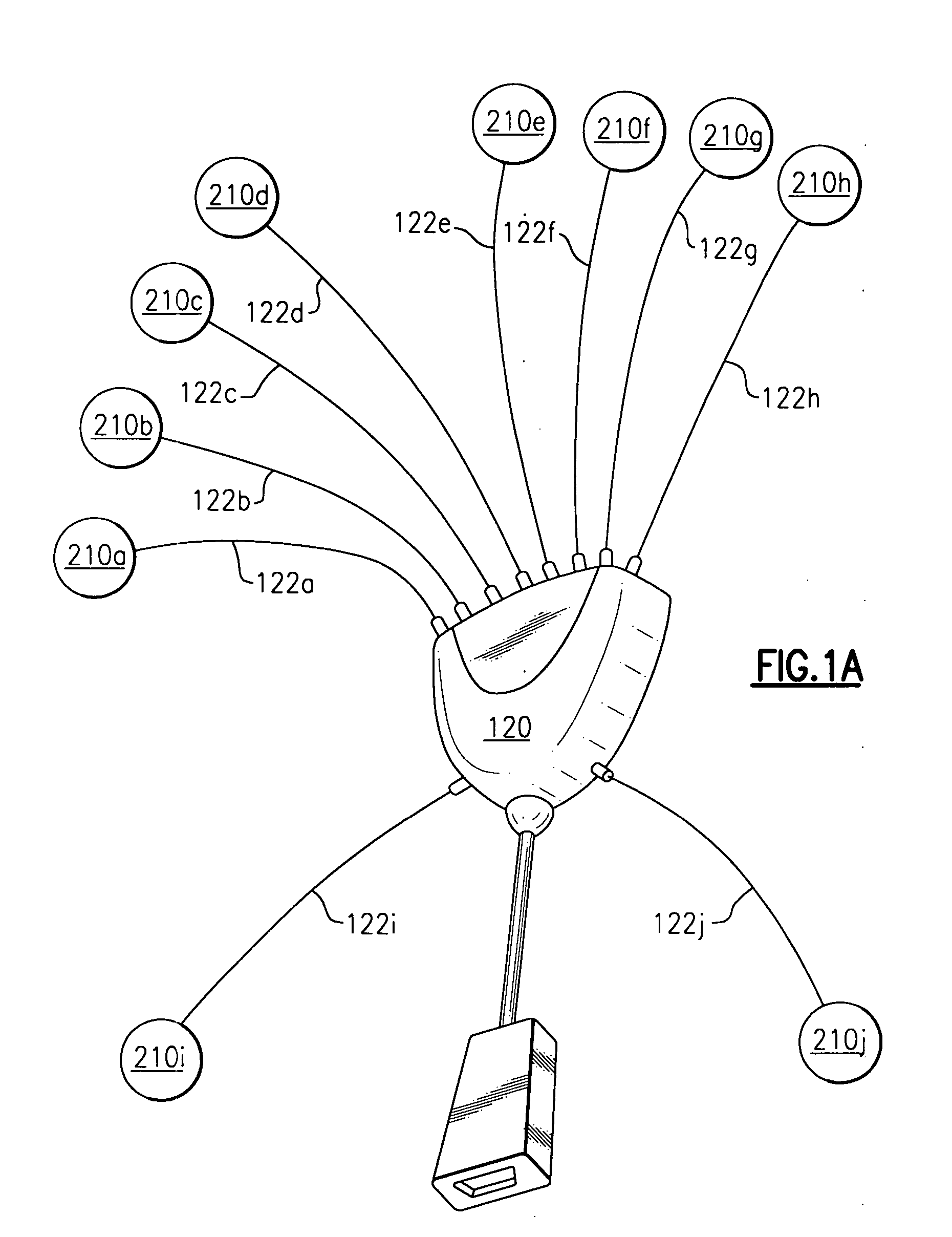
[0013]FIG. 1A is a top conceptual view of an embodiment of an ECG monitoring apparatus 120 including (10) ECG patient contact lead wires 122a-122j that include patient contact electrodes 210a-210j and that are configured to be attached to a person, also referred to as a patient. When the ECG lead wires 122a-122j are attached to the patient, the ECG signals generated by the patient (not shown) are received by the patient contact lead wires 122a-122j and processed by the ECG monitoring apparatus 120. The (8) ECG lead wires 122a-122h are configured to make contact with the upper body (chest and arms) of the patient. The (2) lead wires 122i-122j are configured to make contact with the lower body (legs) of the patient.

[0014] In some circumstances, the patient may be administered a defibrillation shock (voltage surge), of typically about 2000 volts (200 joules) while being monitored by the ECG monitoring apparatus 120. A defibrillation shock can arrest instabilities of cardiac activity o...


PUM


Abstract

A method and apparatus for providing galvanic isolation for signal communication between two electrical circuits via a capacitive coupler that is constructed from conductive and non-conductive layers of a printed circuit board. The invention can provide at low cost and with substantial galvanic isolation, the communication of data at rates of greater than 1 megabit per second. The galvanic isolation provided by the invention protects against common mode fields as well as limited differential mode fields. The invention makes use of pre-existing layers of a circuit board and does not require many other or expensive electrical components.

Description

CROSS-REFERENCE TO APPLICATIONS INCLUDING RELATED SUBJECT MATTER [0001] This application includes subject matter that is related to subject matter included within U.S. design patent application Ser. No. 29 / 217,149 filed Nov. 12, 2004 (attorney docket number 281—443).FIELD OF THE INVENTION [0002] This invention relates generally to providing galvanic isolation for communication of a signal between two electrical circuits, and in particular to providing galvanic isolation for communication of a signal within a medical device, such as for communication of an ECG signal between two electrical circuits via a capacitive coupler that is constructed from at least some of the conductive and non-conductive layers of a printed circuit board. BACKGROUND OF THE INVENTION [0003] Medical devices are typically operated inside of a health care environment in close proximity to patients, other electrical devices and other objects made of conductive material. As a result, there is a risk of unwanted t...

Claims


Application Information

Patent Timeline
IPC IPC(8): H04B3/00
CPCA61B5/04085A61B5/04286A61B5/282A61B5/303A61B5/308
Inventor RUIZENAAR, RUDOLF P.LOOIJE, ALEXIUS O.CUIPYLO, WILLIAM N.
Owner WELCH ALLYN INC
Learn More