
Rapid charge lithium ion battery charger

a lithium ion battery and charger technology, applied in the field of battery chargers, can solve the problems of changing resistance of the various resistance elements, affecting the charging efficiency and limiting the charging current of the battery cell, so as to reduce the charging time of lithium ion batteries

Active Publication Date: 2007-04-05
INT COMPONENTS
View PDF33 Cites 56 Cited by
  • Summary
  • Abstract
  • Description
  • Claims
  • Application Information

AI Technical Summary

Benefits of technology

The present invention is about a circuit that can quickly charge a lithium ion battery. It compensates for the voltage drop and anticipated resistance in the circuit, which ensures a maximum and constant current for efficient battery charging. The circuit also monitors the battery voltage and reduces the charging voltage to the recommended maximum when the battery voltage reaches a predetermined value to safely charge it.

Problems solved by technology

The charging current is limited by the circuit to a design level, based on the cell capability, charge time, needs and cost.
As such, during the last portion of the charging cycle, typically about the last ⅓, the battery cell is charged at a reduced charging current, which means it takes more time to fully charge the battery cell.
Unfortunately, the resistance of the various resistance elements change over time due to various factors including oxidation of the external battery contacts used to connect the battery cell to the battery charger.
Unfortunately when the battery is being charged at a reduced current level, the amount of time required to fully charge the battery is increased.
Unfortunately, the battery charging circuit disclosed in the '237 patent does not take into account the changes in the series resistance values in the circuit over time and thus the effectiveness of the circuit to rapidly charge a lithium ion battery wanes over time as the resistance of the series resistancec elements increases.

Method used


Image

  • Rapid charge lithium ion battery charger
  • Rapid charge lithium ion battery charger
  • Rapid charge lithium ion battery charger

Examples


Embodiment Construction

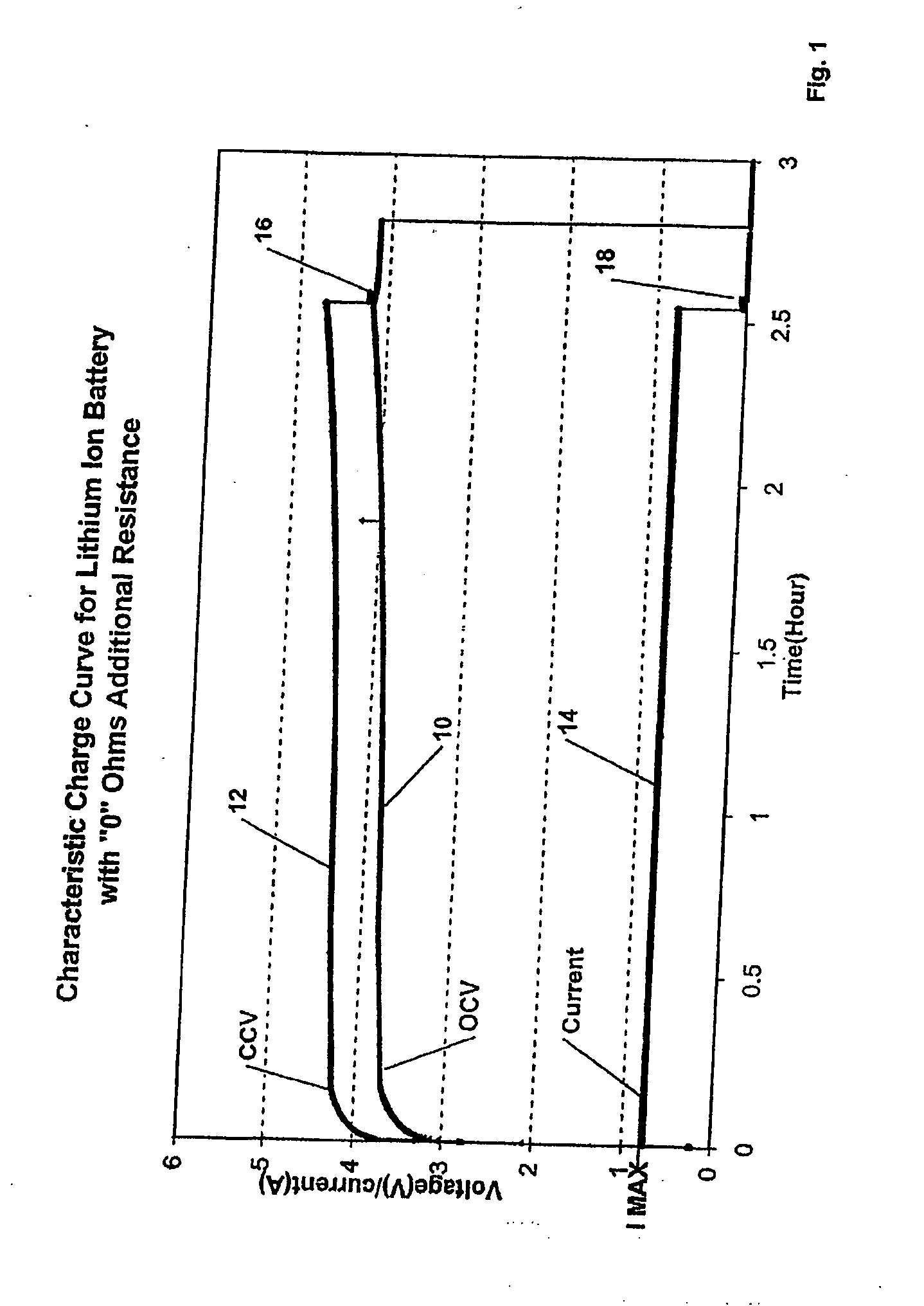
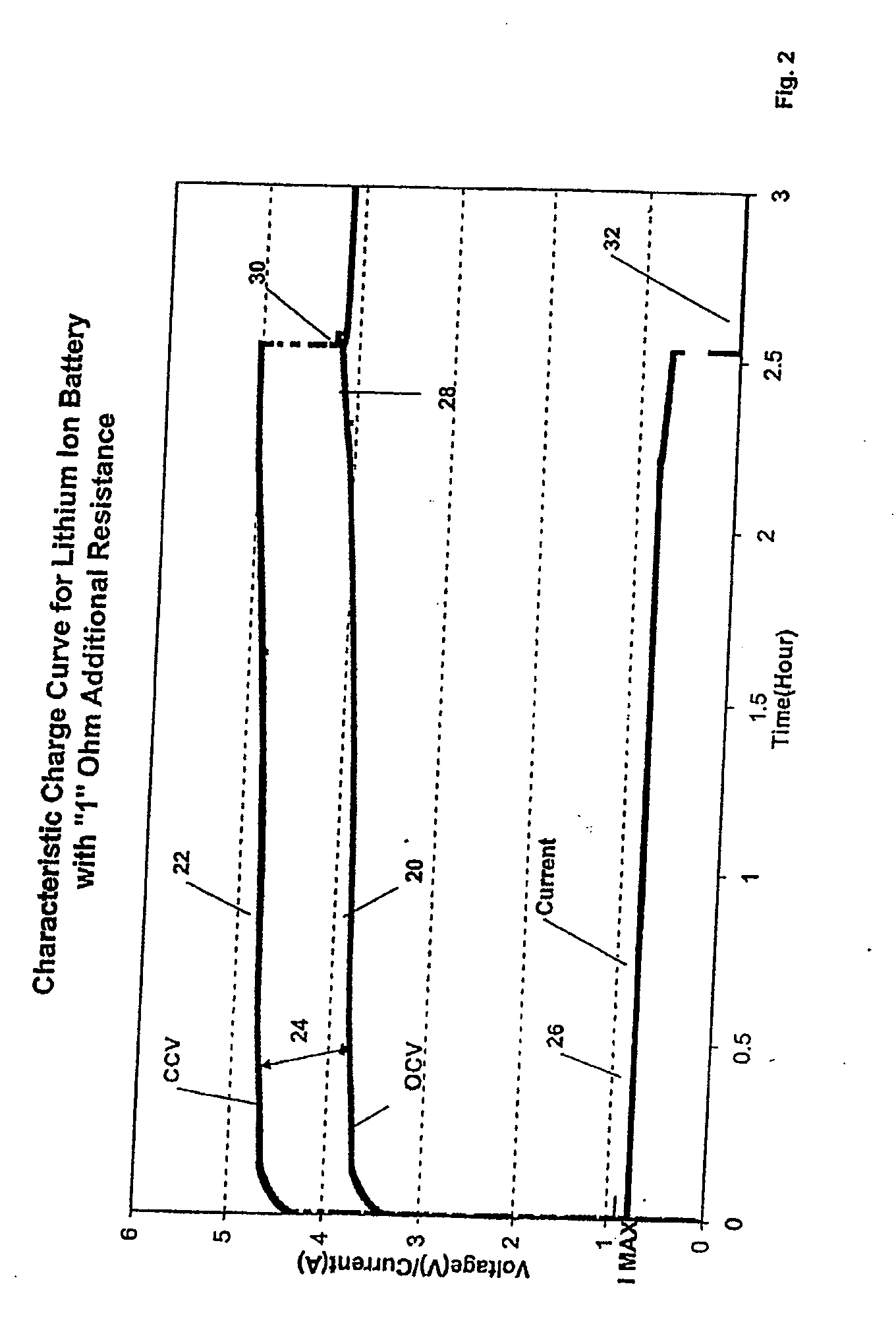
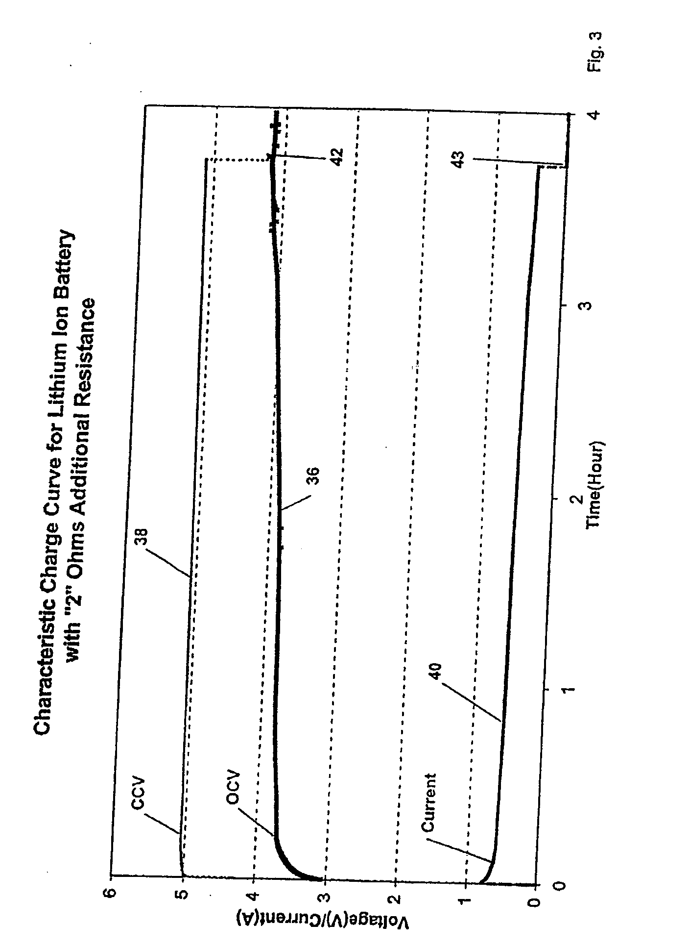
[0022] The present invention relates to a battery charger circuit and, in particular, a battery charger circuit for rapidly charging lithium ion battery cells. As is known by those ordinarily skilled in the art, such lithium ion batteries are charged in a constant current mode and in a constant voltage mode. In accordance with an important aspect of the invention, the battery charger circuit provides and maintains a constant and maximum charging current to the battery cell which not only compensates for the initial resistance of the series resistance elements but also the anticipated increase in resistance of the circuit over time, foe example due to oxidation of the battery cell contacts to provide rapid charging over the antipated resistance change of the circuit. By taking into account the maximum anticipated resistances in the battery charging circuit, the battery charger circuit is configured to provide a charging voltage level, that is able to provide a maximum and constant ch...


PUM


Abstract

A rapid charging circuit for a lithium ion battery. The battery charger in accordance with the present invention compensates for the voltage drops across the various resistance elements in the battery circuit by setting the charging voltage to a level to compensate for the initial resistance of the series resistances in the circuit and an additional resistance selected to take into account the anticipated increase in resistance of the various circuit elements over time. The battery charger in accordance with the present invention periodically monitors the open-circuit voltage of the battery cell and reduces the charging voltage to when the battery cell voltage reaches the optimal value. Thus, during a constant current charging mode, the battery cell is driven at a relatively optimal charging current to reduce the charging time. As such, the system is able to optimize the charging current supplied to a battery cell during a constant current mode of operation while compensating for circuit elements whose resistance may vary over time due to temperature or other factors, such as corrosion, while at the same time avoiding exceeding the maximum recommended voltage for the battery cell.

Description

BACKGROUND OF THE INVENTION [0001] 1. Field of the Invention [0002] The present invention relates to a battery charger and, more particularly, to a battery charger for rapidly and safely charging lithium ion batteries which automatically compensates for anticipated changes of the resistance of the battery charging circuit (i.e. external battery terminals, wires, and internal battery cell resistance) over time, due to, for example, oxidation of the external battery contacts, and provides a maximum and constant current to a battery cell over the anticipated resistance range of battery charging circuit in order to minimize the charging time of the battery cell. [0003] 2. Description of the Prior Art [0004] Battery chargers for charging lithium-ion-type batteries are known in the art. Examples of such battery chargers are disclosed in U.S. Pat. Nos. 5,670,862; 6,002,237 and 6,859,014. Such lithium ion battery chargers are also disclosed in U.S. Patent Application Publication Nos. U.S. 2...

Claims


Application Information

Patent Timeline
Patent Type & Authority Applications(United States)
IPC IPC(8): H02J7/00
CPCH02J7/0077H02J7/0086Y02B40/90Y02E70/40H02J7/00712H02J7/007182Y02B40/00Y02E60/10Y02E60/13
Inventor GUANG, HUANG TAIWENTINK, ROBERT F.JIE, XIA JUHUA, LI WEN
Owner INT COMPONENTS
Learn More