
Method and device for the regulated feed of pulverized fuel to an entrained flow gasifier

a technology of pulverized fuel and regulated feed, which is applied in the direction of combustible gas production, lighting and heating apparatus, and combustion types, etc., can solve the problems of adverse effects, pressure fluctuations, and constant amount of dust flowing per unit tim

Active Publication Date: 2007-04-05
SIEMENS ENERGY GLOBAL GMBH & CO KG
View PDF4 Cites 43 Cited by
  • Summary
  • Abstract
  • Description
  • Claims
  • Application Information

AI Technical Summary

Benefits of technology

The invention provides a method for constant infeed of pulverized fuel into a gasification reactor or other component. This method compensates for fluctuations in pressure differentials between the metering tank and burners of the gasification reactor by introducing auxiliary gas into the transport lines. The amount of auxiliary gas required is determined by measuring the dust flow and adjusting the pressure differentials. The flow velocity of the dust stream should be regulated within a certain range. The invention allows for a constant dust flow rate and maintains metering accuracy with fluctuations in the filled level. The transport lines can be positioned horizontally or vertically, and the pressure in the transport lines can be between 1 and 60 bar. The diameter of the transport lines can vary between 10 and 70 mm, depending on the transport output. The invention can also be used for other users such as blast furnaces.

Problems solved by technology

A problem with this technology is that the amount of dust flowing per unit time must be constant in order to be able to perform reliably in the necessary temperature range for the process of gasification that occurs with an oxidizing medium containing free oxygen.
In particular, the discontinuous loading of the metering tank from the pressurized sluices produces pressure fluctuations that have adverse effects on the pressure differential that serves as the driving force for conveying between the metering tank and the burners of the gasification reactor.

Method used


Image

  • Method and device for the regulated feed of pulverized fuel to an entrained flow gasifier
  • Method and device for the regulated feed of pulverized fuel to an entrained flow gasifier
  • Method and device for the regulated feed of pulverized fuel to an entrained flow gasifier

Examples


Embodiment Construction

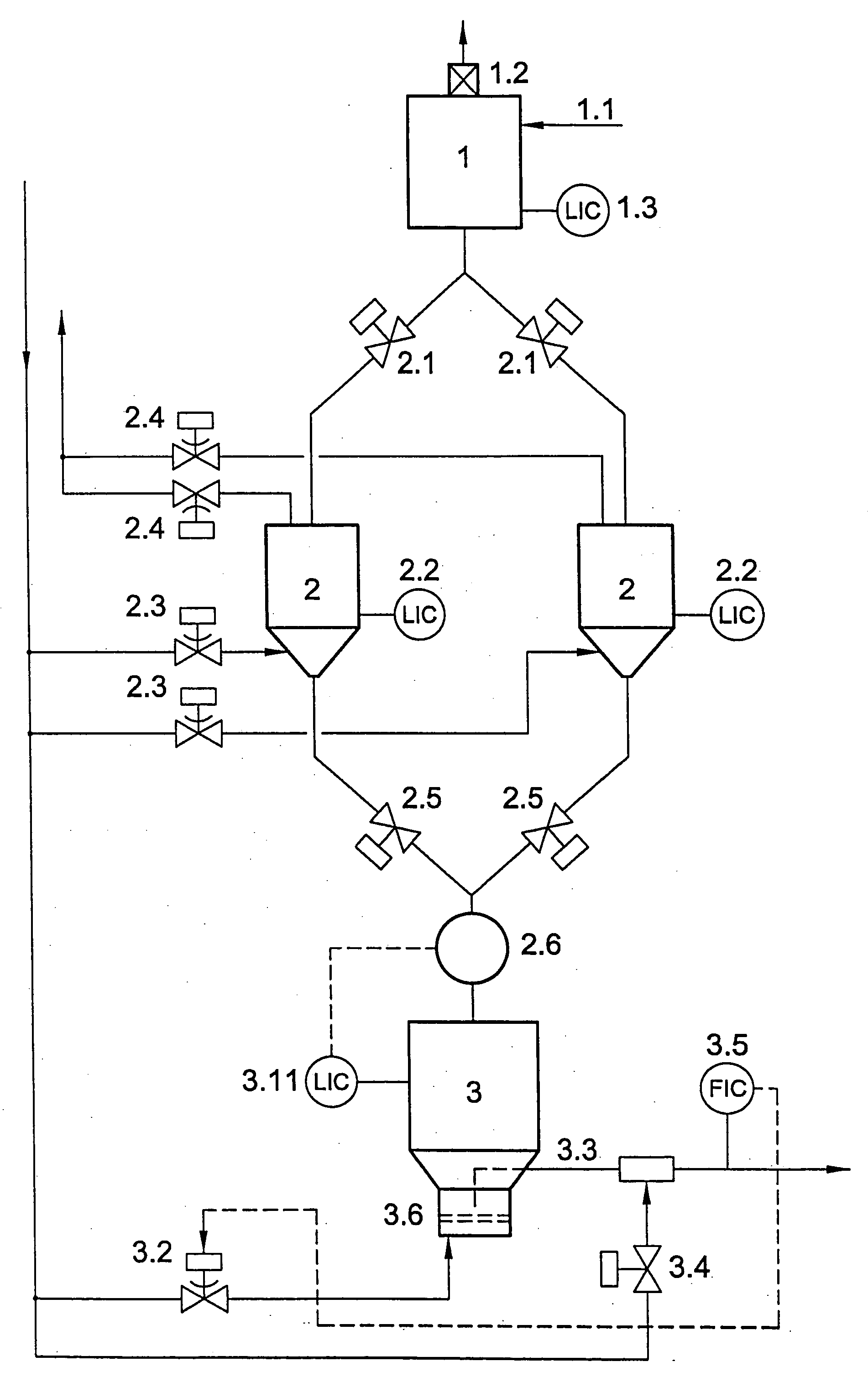
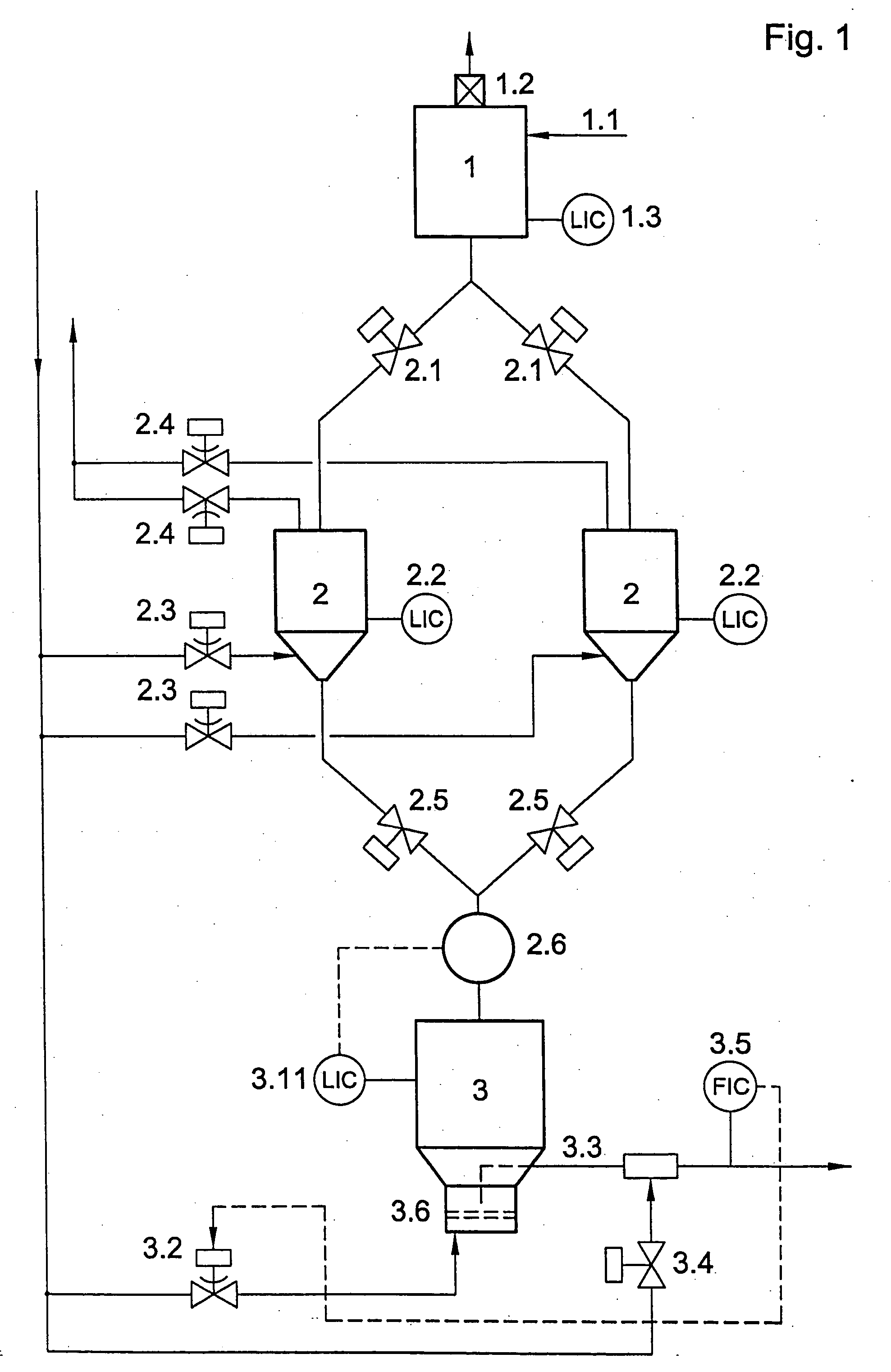
[0017] Referring now in detail to the drawings, FIG. 1 shows a diagram of the technology for dust transport under pressure as it is known in the prior art.

[0018] An entrained flow gasifier (not shown) is operated under a pressure of 40 bar with an output of 500 MW. For this purpose, bituminous coal dust brought to a grain size of 1 through the transport line 1.1 by normal conveyance at low concentration, with the amount supplied being regulated in the level control 1.3. The transport gas is filtered in the filter 1.2 and released to the atmosphere or recompressed and again utilized for conveyance. Since the gasification reactor 4 is operated at 40 bar, the pulverized fuel has to be brought to this pressure. To do this, pressure sluices 2 are loaded alternately with dust and pressurized with inert gas through the lines 2.3. Level regulators 2.2 prevent overfilling. The fittings 2.1 provide pressure-tight blocking toward the operational bunker 1. When the level in the metering tank 3...


PUM


Abstract

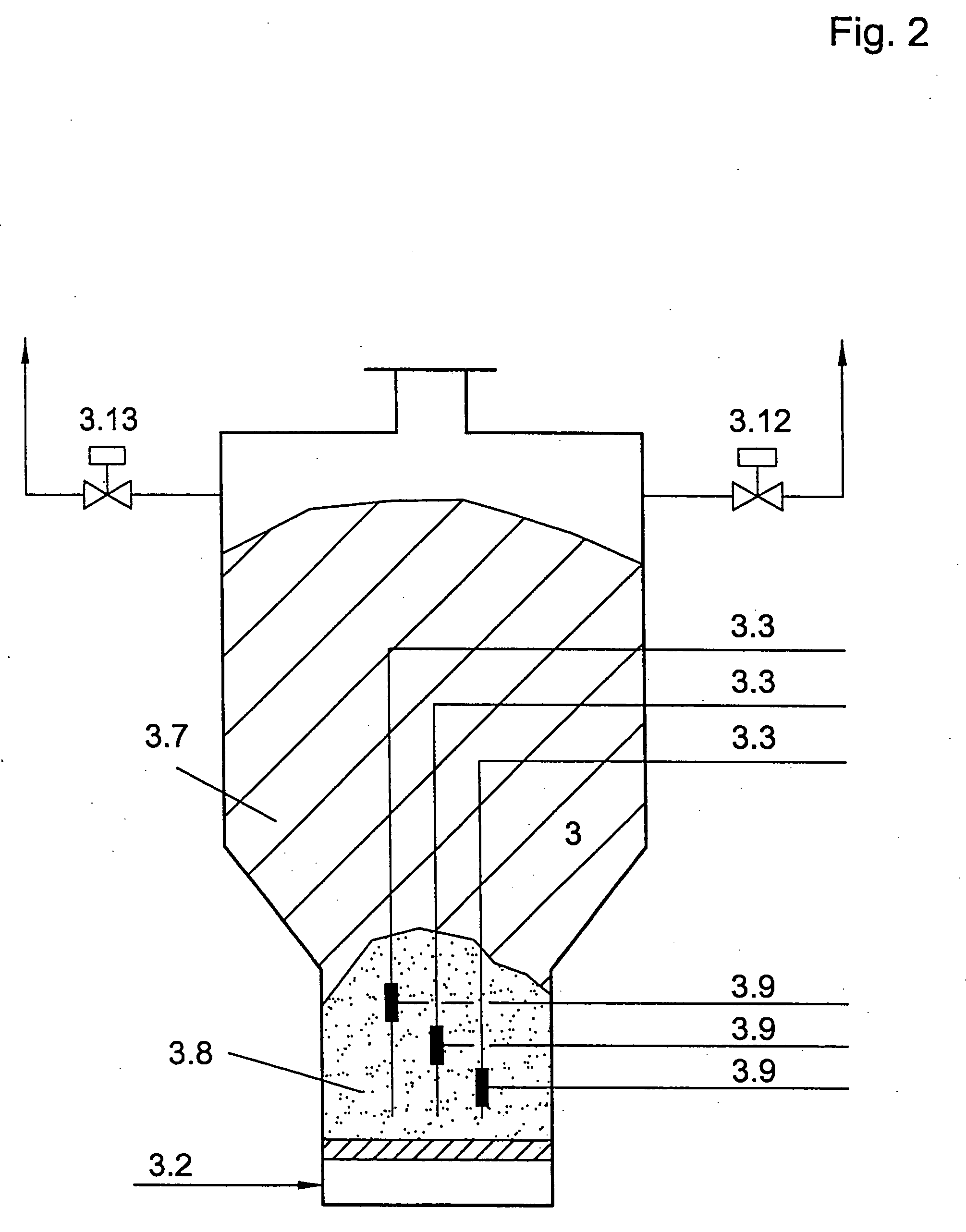
A method and device for metering and feeding pulverized fuels under pressure into gasification reactors, with the pulverized fuel being supplied alternately from an operational bunker through pressurized sluices to a metering tank, in the bottom of which a dense fluidized bed is formed by introducing fluidizing gas through a turbulence plate, with transport pipes immersed in the fluidized bed horizontally or vertically, by which the fluidized fuel is fed continuously through burners to a pressurized gasification reactor. By feeding in auxiliary gas in the immediate vicinity of the transport line inlet into the metering tank or the transport lines, the pressure differential between the metering tank and the gasification reactor is controlled and is utilized as a control parameter for pulverized fuel transport.

Description

BACKGROUND OF THE INVENTION [0001] 1. Field of the Invention [0002] This invention relates to a method for the regulated feed of pulverized fuel for pressurized gasification in an entrained flow gasifier, and a device for implementing the method. [0003] Pulverized fuel means coals of highly varied degrees of carbonization pulverized to the fineness of dust, such as bituminous coals and lignites, pulverized biomasses, cokes produced by thermal pretreatment including petroleum coke but also combustible residues and wastes from industry, domestic sources, and business trades that can be pulverized. [0004] 2. The Prior Art [0005] Methods for pressurized gasification of dust-like fuels are known, in which the dust is fed through a pressurized sluice tank to a metering tank at gasification pressure, from which the pulverized fuel is fed through transport lines to the burner of the gasification reactor as a dust-carrier gas suspension with high loading densities between 250 and 450 kg / m3. ...

Claims


Application Information

Patent Timeline
Patent Type & Authority Applications(United States)
IPC IPC(8): F23K3/00F23G5/00
CPCC10J3/485C10J3/506C10J3/723C10J2200/156F23H5/00F23K3/02
Inventor TIETZE, GUNTERRICHTER, STEFANIESCHINGNITZ, MANFREDHOLLE, BERND
Owner SIEMENS ENERGY GLOBAL GMBH & CO KG
Learn More