
Switching device and system

Inactive Publication Date: 2007-03-22
LEXMARK INT INC
View PDF22 Cites 5 Cited by
  • Summary
  • Abstract
  • Description
  • Claims
  • Application Information

AI Technical Summary

Benefits of technology

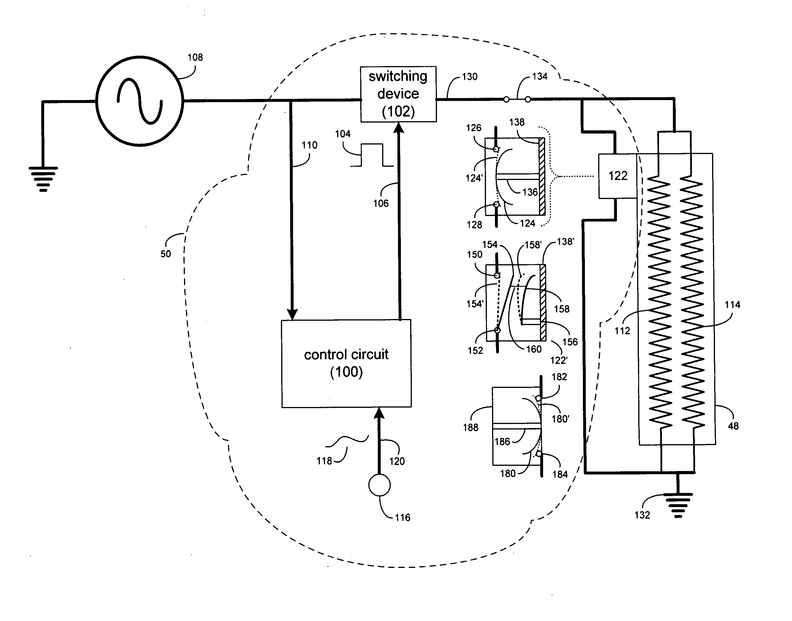
[0007] In a second exemplary embodiment, a bimetallic switching device for a heating device in a printer includes a bimetallic element configured to be coupled to the heating device. The bimetallic element is efficiently thermally coupled to the heating device and configured to deenergize the heating device in the event of an over temperature condition.

Problems solved by technology

Unfortunately, in the event of a failure of the controller circuit, an over temperature condition may occur.

Method used


Image

  • Switching device and system
  • Switching device and system
  • Switching device and system

Examples


Embodiment Construction

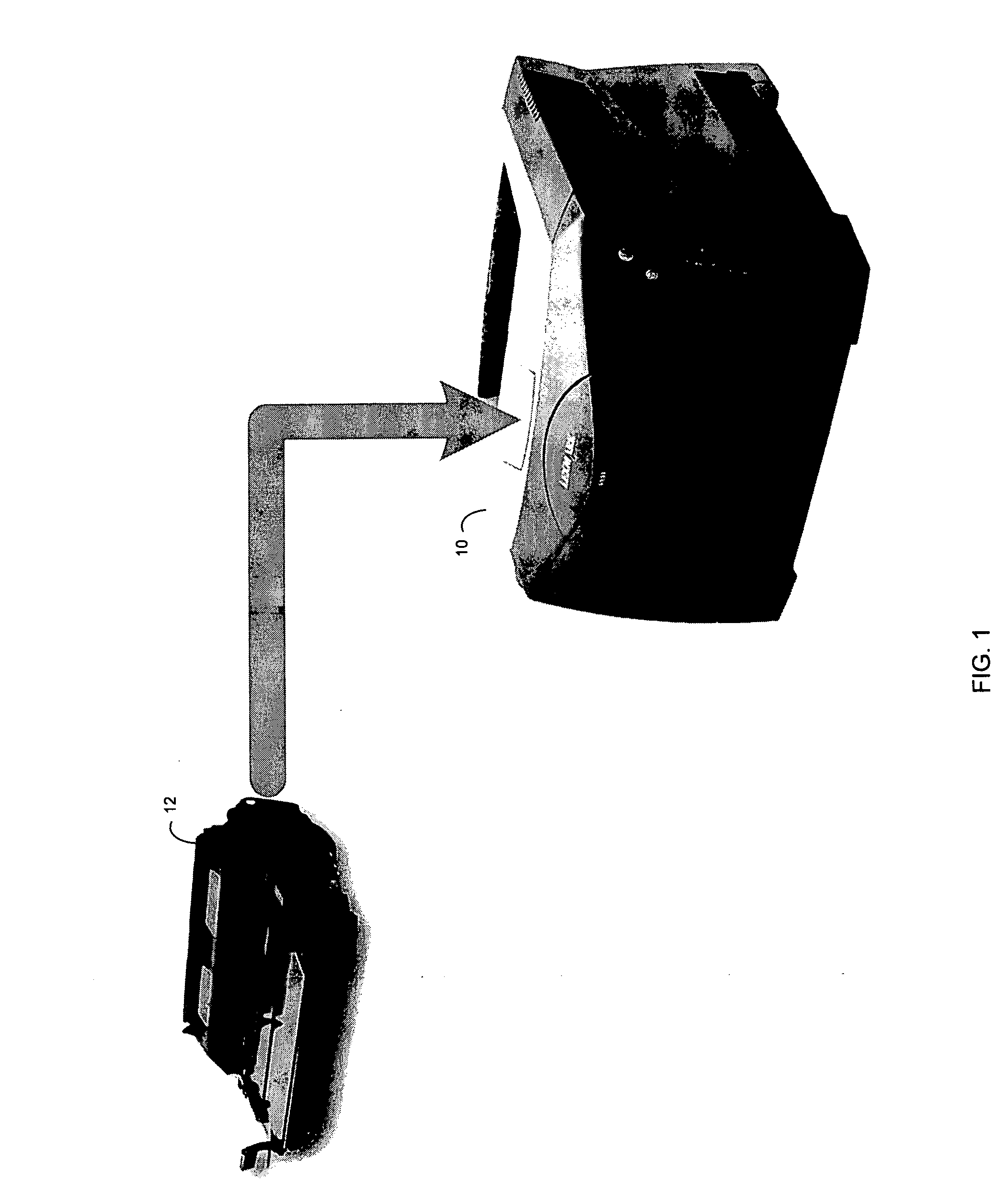
[0019] Referring to FIG. 1, there is shown an exemplary printing device 10 and an exemplary printer cartridge 12 for use within printing device 10. Printing device 10 may be coupled to a computing device (not shown) via e.g. a parallel printer cable (not shown), a universal serial bus cable (not shown), and / or a network cable (not shown). Printing devices herein may include, e.g., electrophotographic printers, ink-jet printers, dye sublimation printers, and thermal wax printers.

[0020] Exemplary printing device 10 is a device that accepts text and graphic information from a computing device and transfers the information to various forms of media (e.g., paper, cardstock, transparency sheets, etc.). Further a printer cartridge 12 is a component of exemplary printing device 10, which typically includes the consumables / wear components (e.g. toner and a drum assembly, for example) of printing device 10. Printer cartridge 12 typically also includes circuitry and electronics (not shown) re...


PUM


Abstract

A heating assembly for a printing device includes a heating device configured to be energized or deenergized. A switching device includes a bimetallic element efficiently thermally coupled to the heating device and configured to deenergize the heating device in a defined period of time in the event of an over temperature condition.

Description

TECHANICAL FIELD [0001] This disclosure relates to switching devices and, more particularly, to a switching device that reacts in response to over temperature conditions which may occur in a printer. BACKGROUND [0002] Printing devices often include heating devices that apply thermal energy to the media being processed by the printing device to e.g., affix toner to the media (i.e., for laser printers) or dry ink applied to the media (i.e., for inkjet printers). Typically, the temperature of these heating devices is regulated through the use of a controller circuit that e.g., monitors the temperature of the heating device and regulates the amount of power provided to the heating device. Unfortunately, in the event of a failure of the controller circuit, an over temperature condition may occur. SUMMARY OF THE DISCLOSURE [0003] In a first exemplary embodiment, a heating assembly for a printing device includes a heating device configured to be energized or deenergized. A switching device...

Claims


Application Information

Patent Timeline
IPC IPC(8): H05B3/00H05B1/02
CPCH05B1/0213H05B1/0241G03G15/2039G03G15/55H05B3/265
Inventor SMITH, JERRY WAYNE
Owner LEXMARK INT INC
Learn More