Leak-proof bottle cap

a bottle cap and leak-proof technology, applied in the field of bottle caps, can solve the problems of introducing contamination to the water inside the bottle, affecting the safety of drinking water, and affecting the safety of drinking water, and achieve the effect of high resilience and durable structur

Inactive Publication Date: 2007-03-22
HUNG MING HUA
View PDF10 Cites 5 Cited by
  • Summary
  • Abstract
  • Description
  • Claims
  • Application Information

AI Technical Summary

Benefits of technology

[0012] The primary object of the present invention is to provide a leak-proof bottle cap with highly...

Problems solved by technology

The main disadvantage of the conventional bottle cap is that the rubber cap will experience material fatigue after prolonged use.
In such a case, the cap B may fall to the ...

Method used


Image

  • Leak-proof bottle cap
  • Leak-proof bottle cap
  • Leak-proof bottle cap

Examples


Embodiment Construction

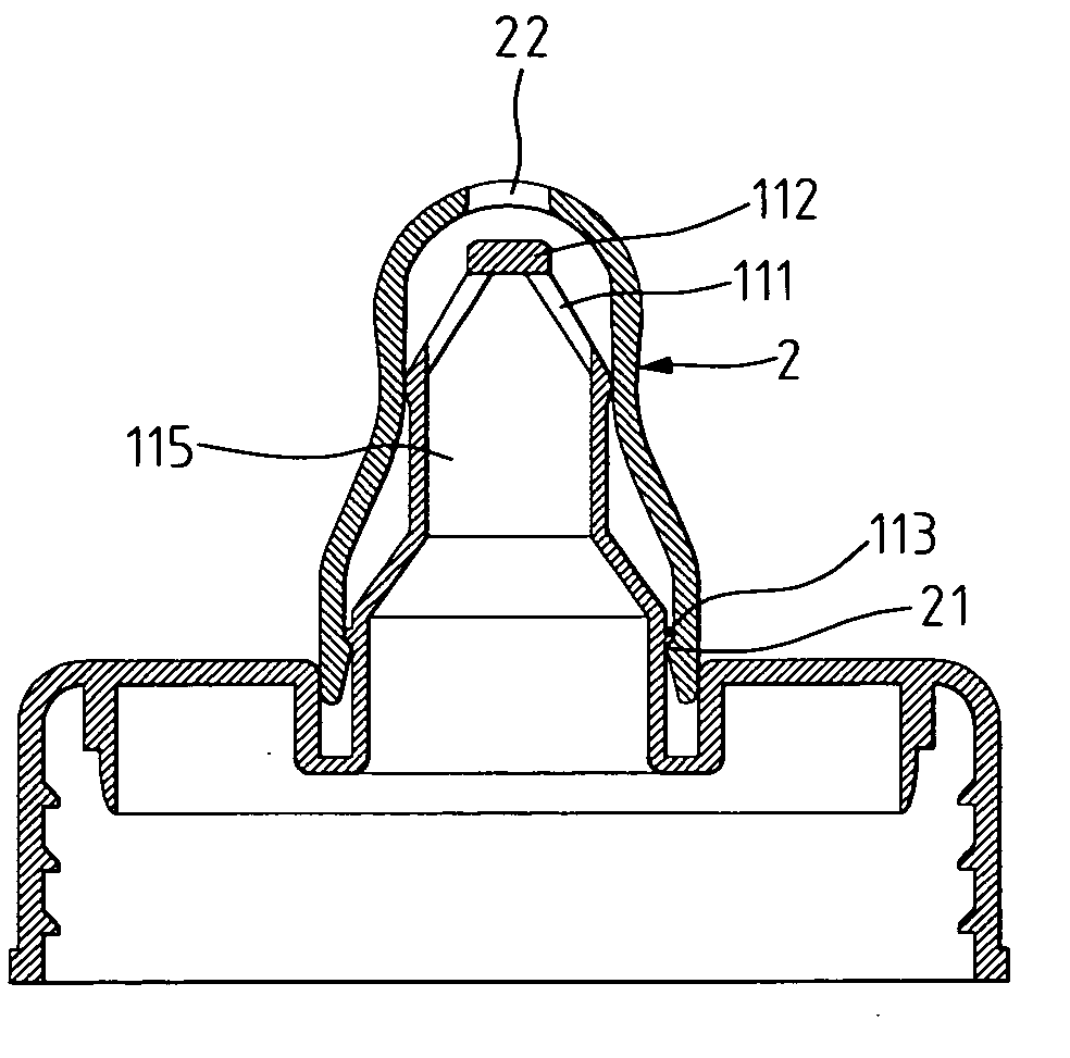
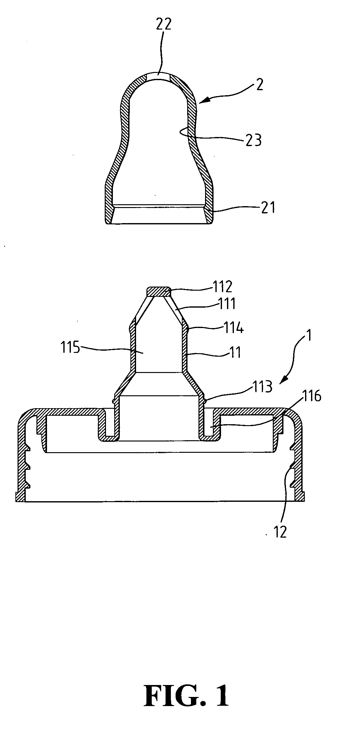
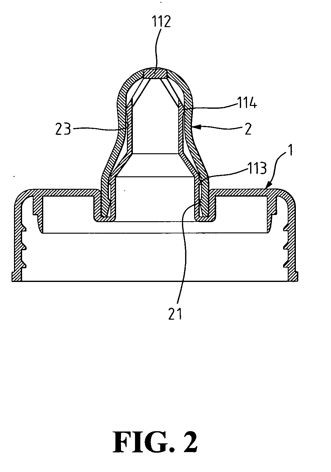
[0024] Referring to FIG. 1, a leak-proof bottle cap in accordance with the present invention comprises a main body 1 and a flanged cap 2. The main body 1 has threads 12 on an inner wall to fit on a mouth of a bottle having outer threads (not shown).

[0025] The main body 1 has a circular base and a flanged column 11 that erects from a center of the circular base and comprises an upper neck with an upper flange 114 on an outside wall and a lower neck with a lower flange 113 on the outside wall, where the outer rim of the upper flange 114 has a smaller diameter than the outer rim of the lower flange 113, forming a step-like column structure.

[0026] A plug 112 is formed at a tip of the flanged column 11, being surrounded by multiple through holes 111 on the upper neck. A circle ditch 116 is formed around a bottom end of the flanged column 11, in between the outer rim of the lower neck and the inner rim of the circular base.

[0027] The flanged cap 2 has an open mouth on one end and an ou...


PUM


Abstract

A leak-proof bottle cap comprises a main body and a flanged cap. The main body has a flanged column vertically connected to a circular base, comprising an upper neck with an upper flange, an lower neck with a lower flange, a fixed plug at a tip, and multiple through holes surrounding the plug. The flanged cap is releasably attached onto the flanged column allowing a mouth end of the flanged cap to be lodged in a circle ditch. The outer rim of the upper flange is in close contact with the inner rim of the flanged cap, and the lower flange acts to block the upward movement of a catch ring on an inner wall of the flanged cap when the flanged cap is pulled up, so the mouth of the flanged cap is always covered by the circle ditch. This structural design can ensure tight sealing of the bottle to prevent spilling in any conditions.

Description

BACKGROUND OF THE INVENTION [0001] 1. Field of the Invention [0002] The present invention relates to a bottle cap that can tightly seal a bottle to prevent any spilling in any conditions. [0003] 2. The Prior Arts [0004] The conventional bottle caps of sport bottles or sipper bottles allow users to pull a plug that covers a center hole of the caps to sip or pour water through the center hole, which means the cap is not physically detached from the bottle when opened. There is a valve mechanism embedded in the bottle cap to control the water flow from the bottle. [0005] Referring to FIGS. 4 and 5, the conventional valve-controlled water bottle comprises a main body A and a ball-shaped cap B. A flanged column A2 is connected to a circular base of the main body A, and has an external flange A21 on an outer wall and multiple ribs supporting a fixed plug A1 in a center thereof. The ball-shaped cap B has two concentric tubes B1, B2 on an underside, where the outer rim of the inner tube B2 ...

Claims


Application Information

Patent Timeline
IPC IPC(8): B65D51/16B67D3/00A47G19/22
CPCB65D47/243A47G19/2272
Inventor HUNG, MING-HUA
Owner HUNG MING HUA
Why Eureka
Try Eureka