Electric vacuum cleaner
- Summary
- Abstract
- Description
- Claims
- Application Information
AI Technical Summary
Benefits of technology
Problems solved by technology
Method used
Image

Examples
first embodiment
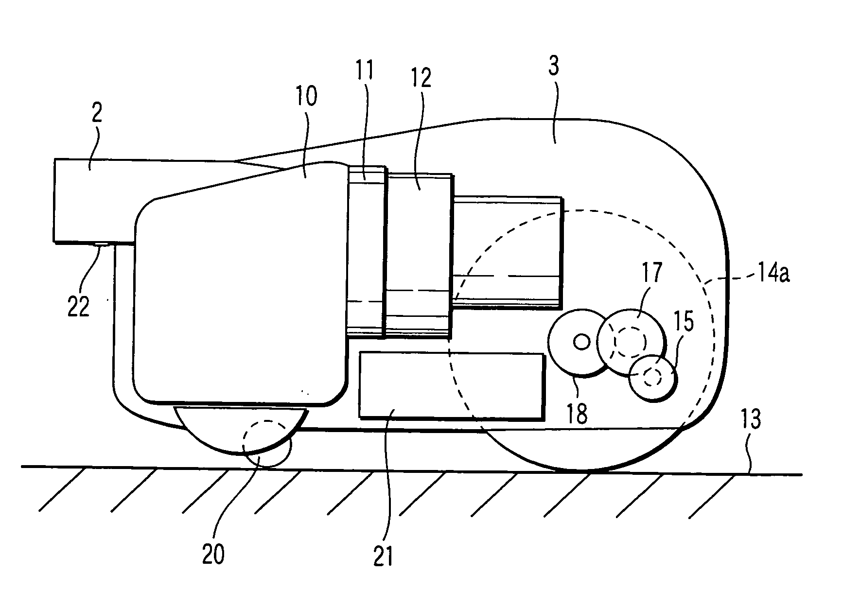
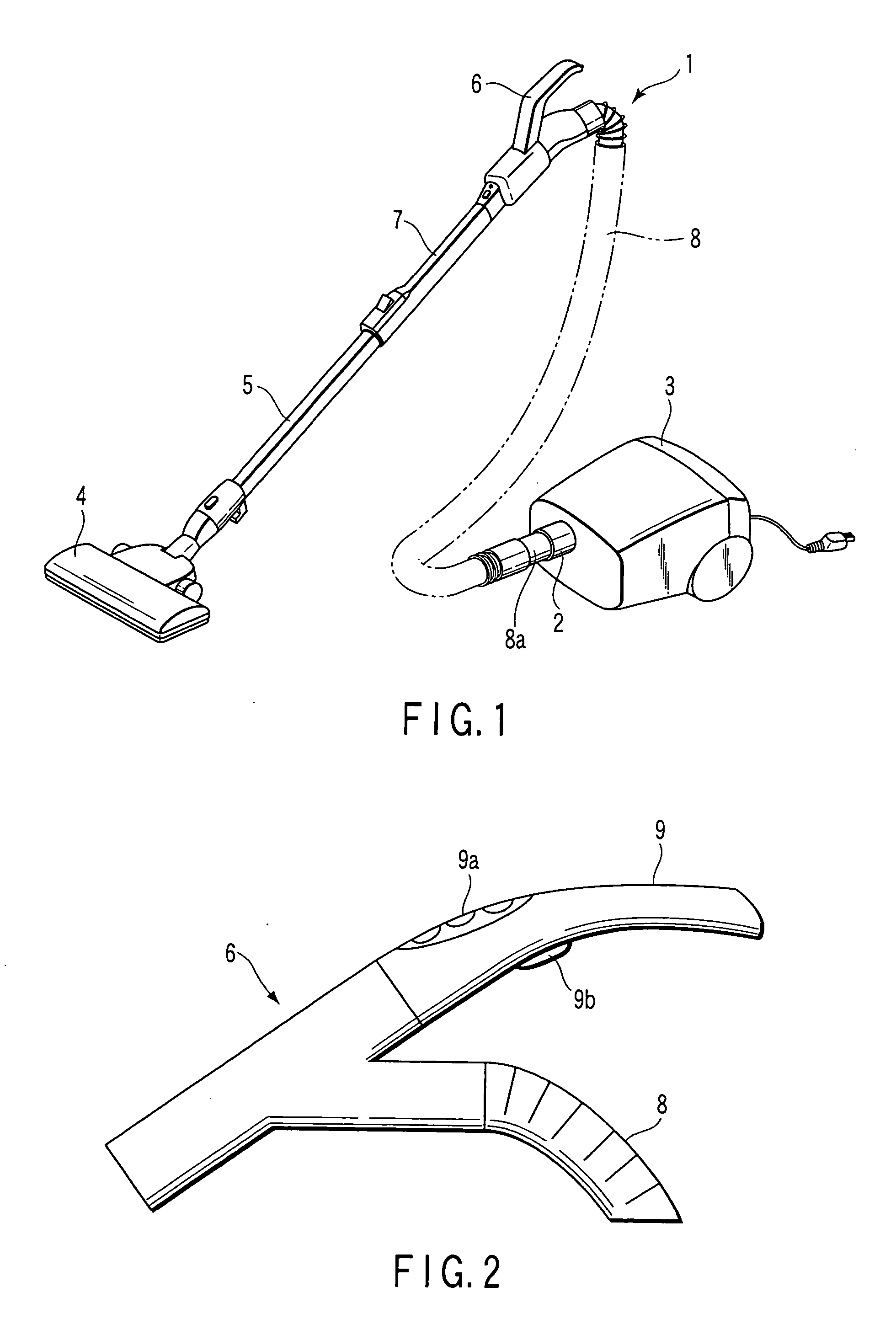
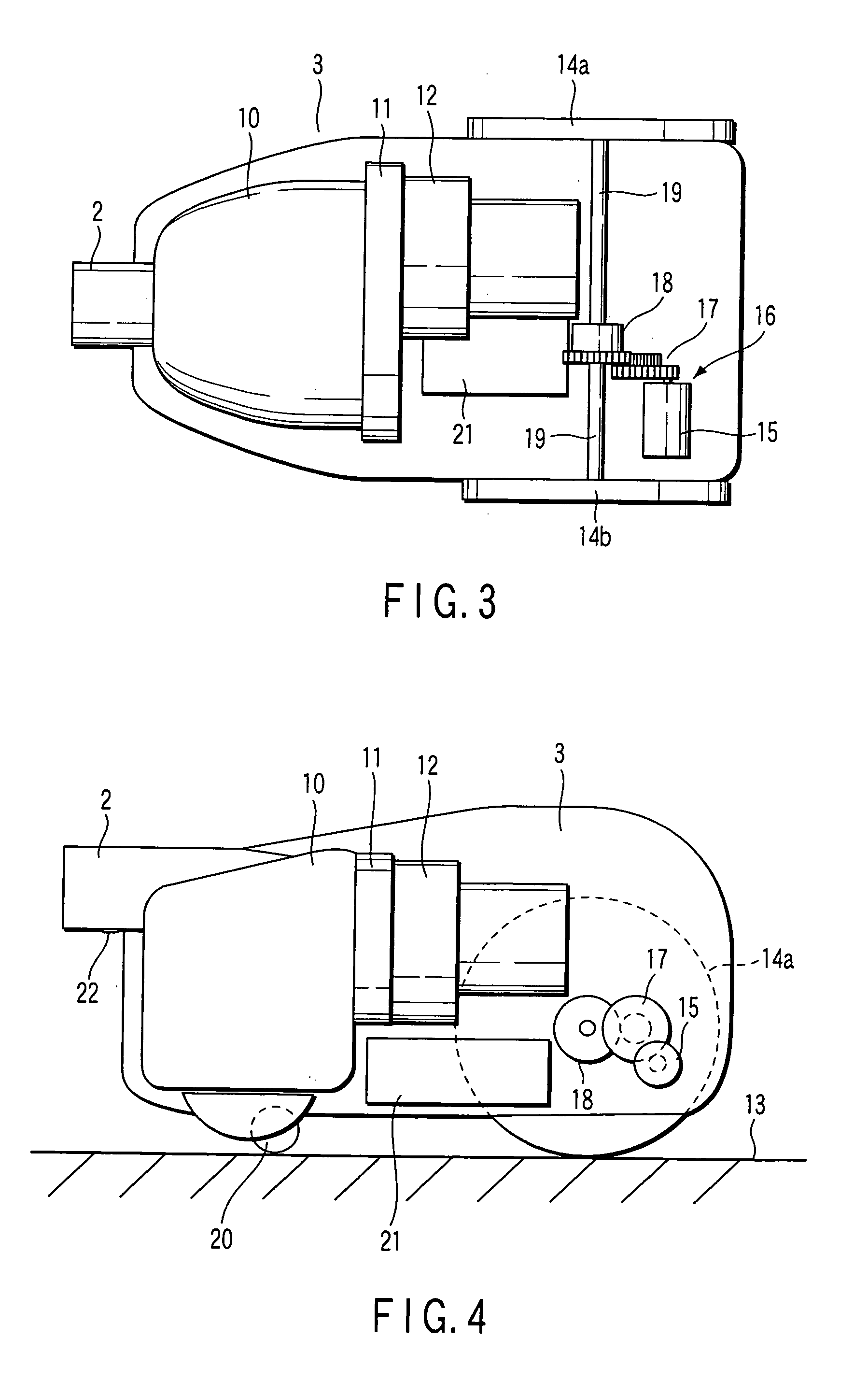
[0028]FIG. 1 is a perspective view showing an overall configuration of an electric vacuum cleaner. The electric vacuum cleaner includes a communicating tube 1 which is formed cylindrically and a vacuum cleaner main body 3. The vacuum cleaner main body 3 has a communicating tube attachment member 2, which is formed cylindrically so as to attach the communicating tube 1.
[0029] The communicating tube 1 includes the first extension pipe 5, the second extension pipe 7, and a hose 8 attaching an operation member 6 at its one end. At one end of the first extension pipe 5, there is provided a suction opening 4, which slides on a floor so as to suction dust. Further, at the other end of the first extension pipe 5, the first extension pipe 5 slidably fits the other end of the second extension pipe 7. The suction opening 4 is detachable from the first extension pipe 5.
[0030] The hose 8 extends from the operation member 6 and is attached to the communicating tube attachment member 2 of the va...
second embodiment
[0073] This embodiment will describe a modification example of attaching the strain gauge 22 to the communicating tube attachment member 2. In addition, the same components as in the above-described embodiment are given the same reference numbers.
[0074] As shown in FIG. 7, the communicating tube attachment member 2 equips cylindrical projections 51 and 52 at two positions, its front and rear on the front surface side. The front projection 51 is made short in its projecting length. The rear projection 52 is made long in its projecting length. And a detecting member 53 to which the strain gauge 22 has been attached is prepared.
[0075] The central portion of the detecting member 53 is formed to be thin and attaches the strain gauge 22 in its center, as shown in FIG. 8. Further, the detecting member 53 equips holes 54 and 55 for fitting the projections 51 and 52 at its front and rear.
[0076] The thickness of the detecting member 53 from the central portion to which the strain gauge 22 ...
third embodiment
[0082] This embodiment will describe a modification example of the communicating tube attachment member to attach the communicating tube 1. In addition, the same components as in the above-described embodiments are given the same reference numbers.
[0083] As shown in FIG. 9, the front end 8a of the hose 8 making up the communicating tube 1 fits a communicating tube attachment member 61 of the vacuum cleaner main body 3. As shown in FIGS. 10 and 11, a rear end 61a of the communicating tube attachment member 61 is cylindrically formed sideways and the communicating tube attachment member 61 is supported pivotally at the vacuum cleaner main body 3. And a front portion which the front end 8a of the hose 8 is fitted to turns upward and downward on the rear end 61a.
[0084] An air trunk communicating between the rear end 61a of the communicating tube attachment member 61 and the dust chamber 10 is so formed that the airflow from the hose 8 enters the dust chamber 10 straight. Instead, the ...
PUM
 Abstract
Description
Claims
Application Information
 - R&D
- Intellectual Property
- Life Sciences
- Materials
- Tech Scout
- Unparalleled Data Quality
- Higher Quality Content
- 60% Fewer Hallucinations
Browse by: Latest US Patents, China's latest patents, Technical Efficacy Thesaurus, Application Domain, Technology Topic, Popular Technical Reports.
© 2025 PatSnap. All rights reserved.Legal|Privacy policy|Modern Slavery Act Transparency Statement|Sitemap|About US| Contact US: help@patsnap.com