Debugging system and method

a multitask environment and debugging system technology, applied in the field of multitask environment debugging system and method, can solve the problems of affecting the operation of tasks, the scale of software embedded in such systems is increasing, and the operation of tasks is affected, and the operation of running tasks may fail

Inactive Publication Date: 2007-03-15
SOCIONEXT INC
View PDF6 Cites 7 Cited by
  • Summary
  • Abstract
  • Description
  • Claims
  • Application Information

AI Technical Summary

Benefits of technology

[0016] Conceived to solve the described problem, the present invention has an object of providing a debugging system and method in which, in a multitask environment, a break setting for a task that is a target of debugging does not affect operations of tasks that are not a target of debugging.
[0022] With the stated structure, debugging setting and cancellation is performed only in the physical address of a task that is a target of debugging setting. Therefore, processing for debugging setting and cancellation when a task switch occurs is minimal, and the processing load required for debugging setting and cancellation can be kept to a minimum.
[0025] With the stated structure, when the debugging settings of the next task and the task that was being run before the switch are made in the same physical address, processing for debugging setting and cancellation can be omitted when the task switch occurs. Therefore, the processing load when a tasks witch occurs can be lightened.
[0028] With the stated structure, when the task being run before a switch and the next task share do not share a physical address space range, debugging cancellation processing when the switch occurs can be omitted. Therefore, the processing load required for debugging cancellation processing can be lightened.

Problems solved by technology

With advances in the functionality and performance of informationappliances, automobilecontroldevices, andthelike in recent years, software embedded in such systems is becoming larger in scale and more complicated.
However, when a plurality of tasks in a multitask environment share memory resources in this way, operations of tasks are affected when processing such as break setting and rewriting of recording content of the memory is performed with respect to another task that is the target of debugging by a debugger.
For instance, a failure may occur in the operations of a running task that is not a target of debugging, due to a break stop occurring based on a break setting set for another task and an instruction rewritten for debugging being executed.
However, with the described technique, when a break occurs in a task that is not a target of debugging, it is necessary to re-run the task.
This is problematic in that it is a hindrance to real-time operation, in other words operation in a set time requirement, of tasks that are not a target of debugging.

Method used


Image

  • Debugging system and method
  • Debugging system and method
  • Debugging system and method

Examples


first embodiment

Structure

Structure of Debugging System

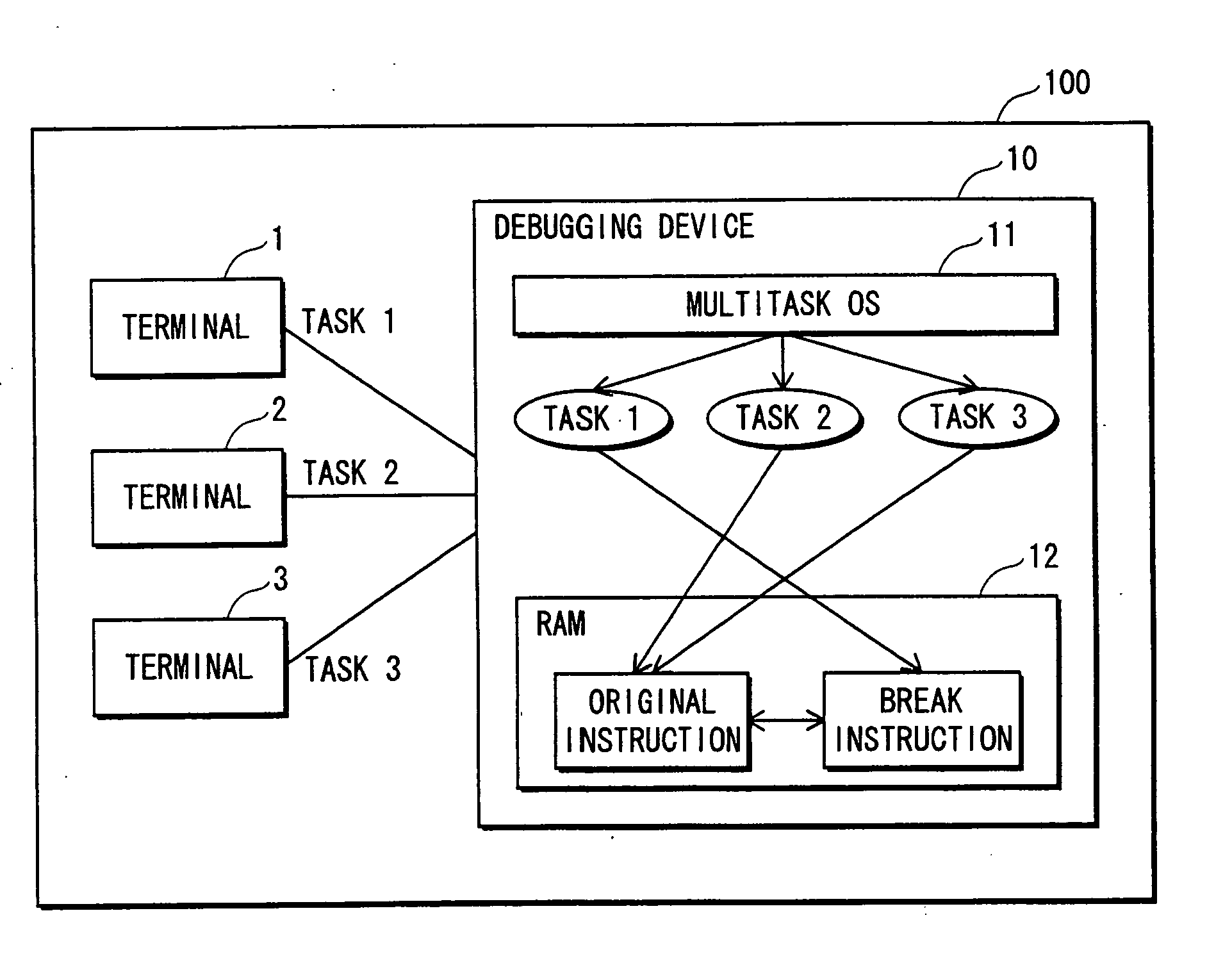
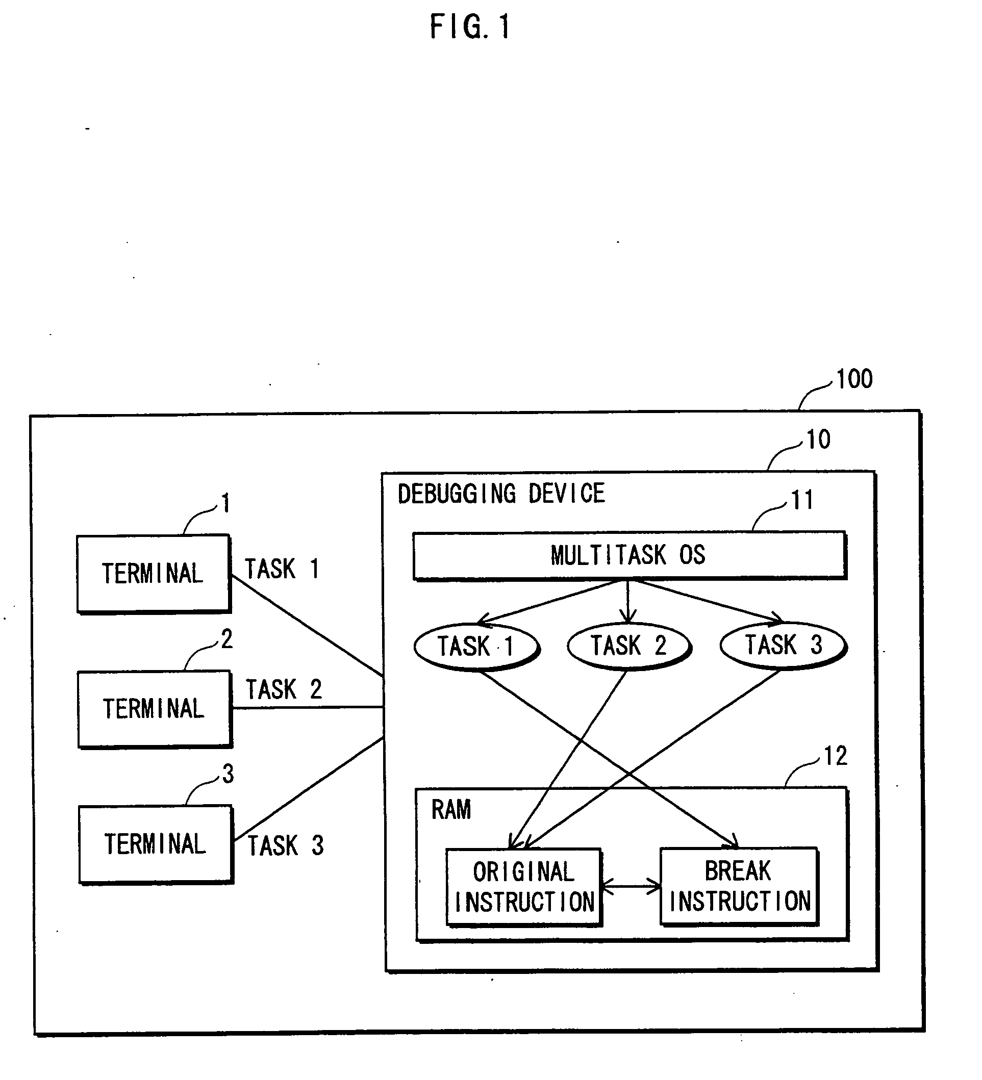
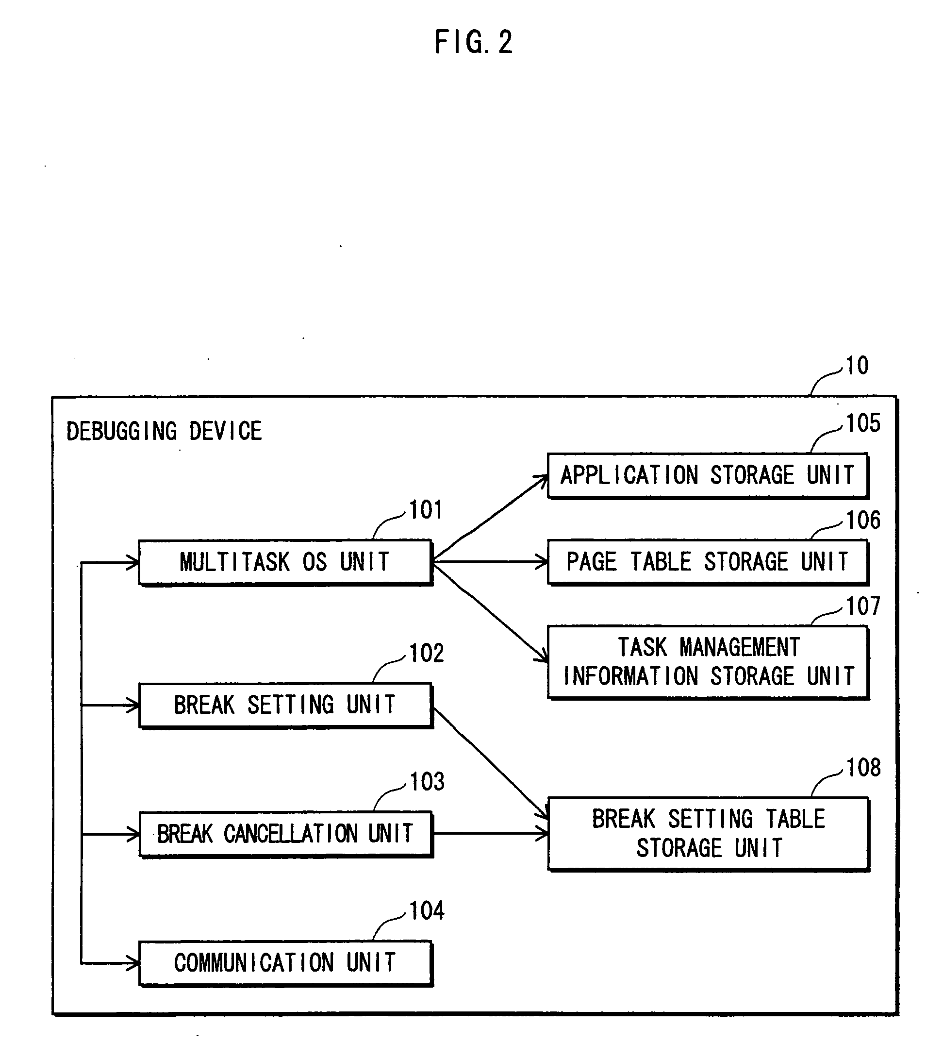
[0057]FIG. 1 is a function block diagram showing the structure of a debugging system 100 relating to the present embodiment. The debugging system 100 is composed of terminals 1 to 3 and a debugging device 10.

[0058] The terminals 1 to 3 are connected to the debugging device 10 with respective communication lines. Each of the terminals 1 to 3 has a function of outputting various commands to the debugging device 10 via the respective communication line, receiving a processing result from the debugging device 10 based on the particular output command, and displaying the result on a display unit (not illustrated).

[0059] The debugging device 10 has a function of loading an application program to a physical address space in a RAM 12 in accordance with an application program execution command from any of the terminals 1 to 3, executing a task by executing the application program under the control of a multitask OS 11, and transmitting the execution ...

second embodiment

[0111] In the debugging system 100 of the first embodiment, break setting processing and break cancellation processing are performed each time a tasks witch occurs. However, in a debugging system 200 of the second embodiment, when a break setting has been made for the next task to be run that is the same as the break setting for the directly preceding stopped task, break setting processing and break cancellation processing when task switching occurs are omitted. This enables task switch processing to be performed quickly. Note that the debugging system 200 differs from the debugging system 100 of the first embodiment only in terms of structure described below, and other compositional elements are identical. Consequently, a function block diagram showing the structure of the debugging system 200 is omitted. This also applies to debugging systems 300, 400 and 500 described later.

Structure

[0112] The following omits a description of the compositional elements that are the same as in t...

third embodiment

[0135] In the debugging system 100 of the first embodiment, break setting processing and break cancellation processing are performed each time a task switch occurs. However, in the debugging system 300 of the third embodiment, when a task switch occurs, all break settings registered in the break setting table are performed first, and then all of the break settings whose physical address differs from that of the task to be run next are cancelled.

Structure

[0136] The following omits a description of the compositional elements that are the same as in the debugging system 100 in the first embodiment, and focuses on those that differ.

Structure of Debugging Device 30

[0137]FIG. 23 is a function block diagram showing the structure of a debugging device 30 included in the debugging system 300. The debugging device 30 is composed of a multitask OS unit 301, a break setting unit 302, a break cancellation unit 303, the communication unit 104, the application storage unit 105, the page table s...


PUM


Abstract

In a multitask execution environment, a debugging device performs debugging setting for rewriting part of original recording content in a memory area shared by at least two tasks, and debugging cancellation for restoring rewritten recording content back to original recording content. The debugging device stores a memory area used by each task, and address information specifying each debugging target task and a respective address. When task switching occurs, if a next task is not a debugging target, recording content at a physical address specified by address information other than that of the next task and within the physical address space range used by the next task is put into a post-debugging cancellation state. If the next task is a debugging target task, in addition to the above processing, recording content at the physical address specified by the address information of the next task is put into a post-debugging setting state.

Description

[0001] This application is based on application No. 2005-267335 filed in Japan, the content of which is hereby incorporated by reference. BACKGROUND OF THE INVENTION [0002] (1) Field of the Invention [0003] The present invention relates to a debugging system and method for a multitask environment, and in particular to a technique for, inanenvironment whereapluralityof tasks access a same memory, controlling such that operations of tasks that access the memory are not affected when recording content of the memory is rewritten as necessary. [0004] (2) Description of the Related Art [0005] With advances in the functionality and performance of informationappliances, automobilecontroldevices, andthelike in recent years, software embedded in such systems is becoming larger in scale and more complicated. This has resulted in increaseduse of operating systems (OSs) in the field of embedded software, and the majority of such OSs are multitask OSs. [0006] Using a multitask OS enables differen...

Claims


Application Information

Patent Timeline
Patent Type & Authority Applications(United States)
IPC IPC(8): G06F11/00
CPCG06F11/3664
Inventor TAKAGI, SHIGEYAHAMADA, YASUHIKOMATSUMOTO, HIDETAKA
Owner SOCIONEXT INC
Why Eureka
Try Eureka