
Lighting energy management system and method

a technology of energy management system and light fixture, applied in the direction of positioning/direction control, instruments, electrical equipment, etc., can solve the problems of over-lit work spaces, high energy consumption of light fixtures, and high lighting costs of lighting designers, so as to minimize the energy required of light fixtures

Inactive Publication Date: 2007-03-15
ENCELIUM TECH
View PDF18 Cites 207 Cited by
  • Summary
  • Abstract
  • Description
  • Claims
  • Application Information

AI Technical Summary

Benefits of technology

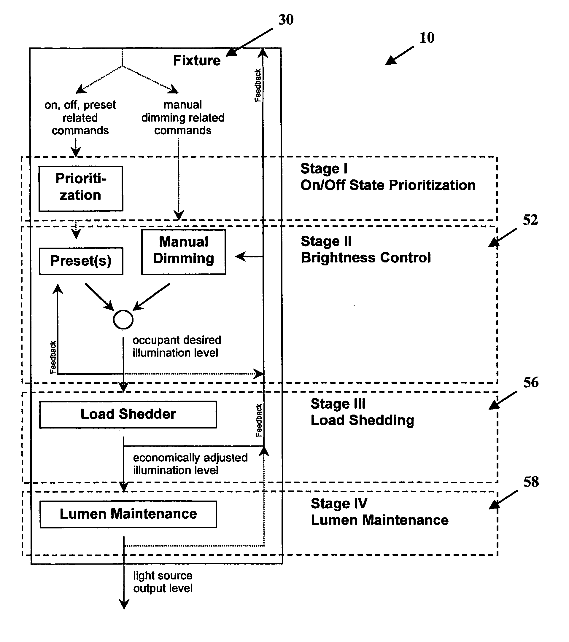
[0022] (i) each said zone object receives occupancy sensor data and selectively provides an adjustment command to at least one associated lighting fixture, so that the optimal brightness command reduces at least one associated lighting fixture in brightness when the zone is determined to be unoccupied;
[0024] (e) distributing the optimal brightness command received from each of said fixture objects to each said associated lighting fixtures, such that the energy required by the light fixtures is minimized according to several individual energy management strategies and personal lighting preferences.
[0049] The invention provides in another aspect a method of controlling the operation of a plurality of energy consuming units in a building using a plurality of local switching devices that reduces switching stress due to excessive inrush currents normally associated with said energy consuming units and reduces energy consumption, each energy consuming unit having an associated power supply and an inrush current limiting impedance, said method comprising:

Problems solved by technology

It is often the case that work spaces are over-lit after a lighting upgrade.
Additionally, lighting designers often provide for too much lighting in an area, as the exact use of a particular area may change over time.
Alternatively, energy might be billed at constantly varying rates in deregulated markets, with such rates showing price spikes in times of power supply shortages.
However, combining these strategies is a difficult and complex matter since the combination of these energy reduction strategies can often result in undesirable effects.
When this is completed, an associated lighting sensor utilized by the daylight harvesting would sense a reduction in illumination and attempt to counteract this, resulting in an inefficient system.

Method used


Image

  • Lighting energy management system and method
  • Lighting energy management system and method
  • Lighting energy management system and method

Examples


Embodiment Construction

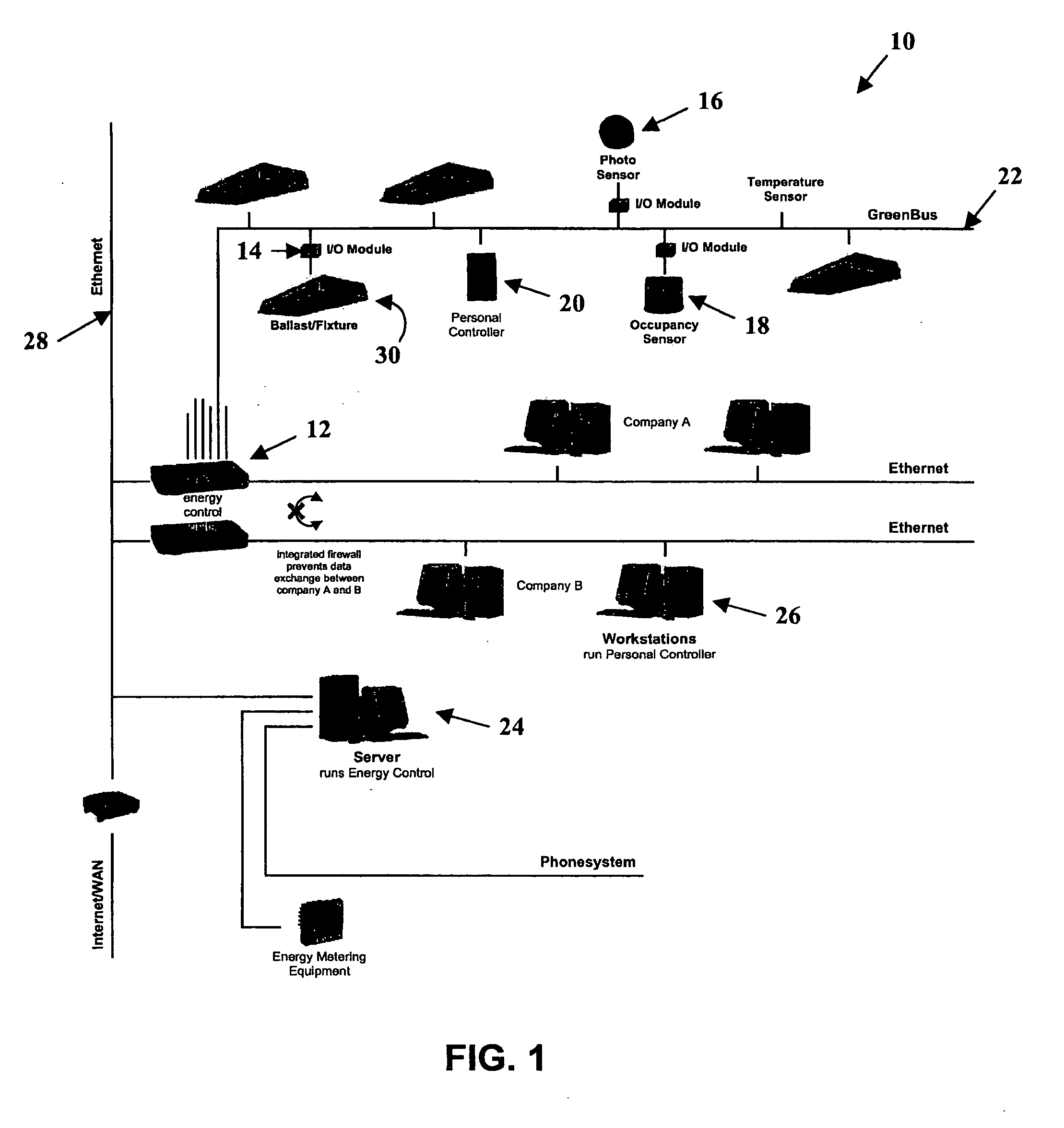
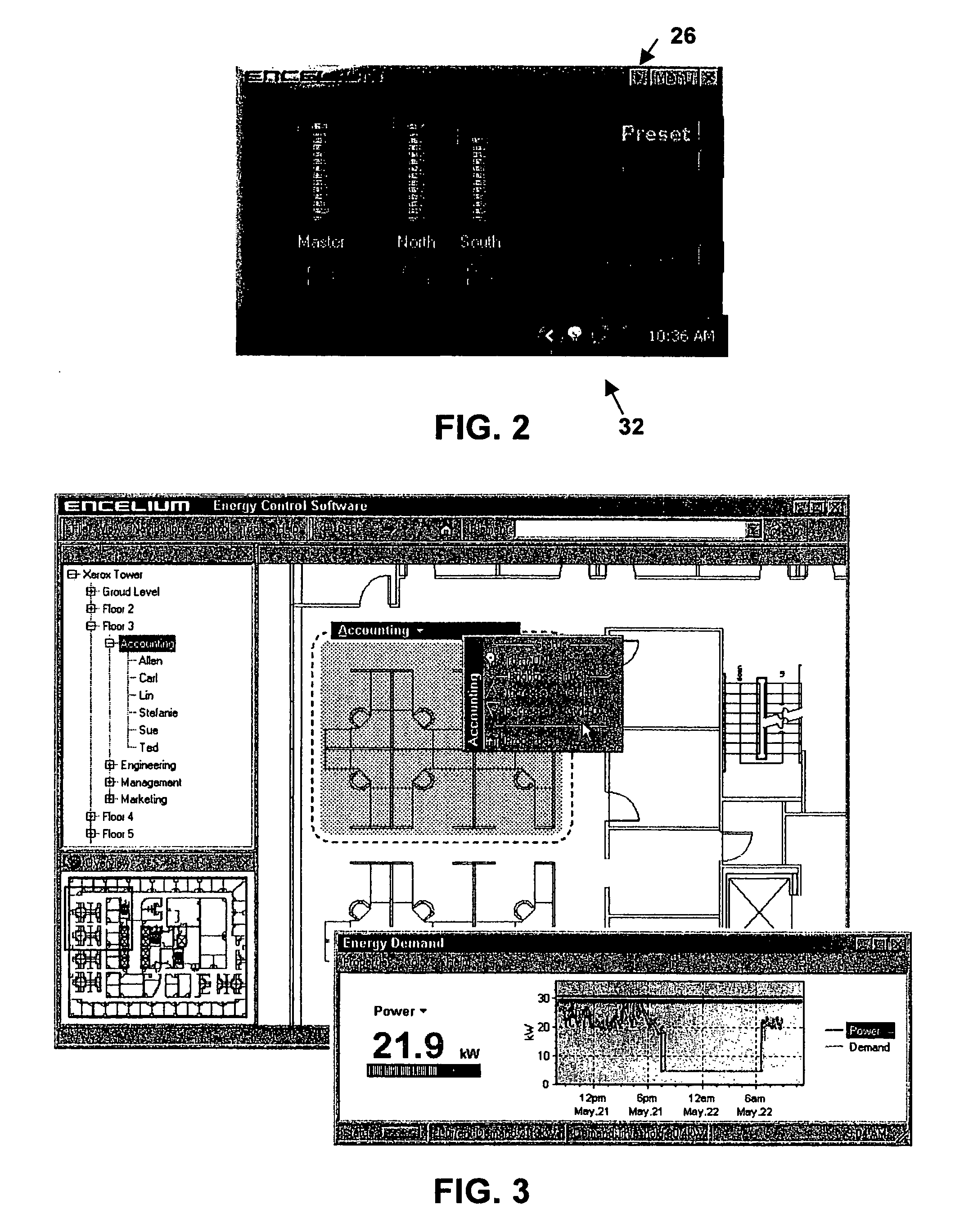
[0074]FIG. 1 is a diagram of a lighting energy management system 10 made in accordance with a preferred embodiment of the invention. Energy management system 10 contains energy control units (ECU) 12, universal input / output modules 14, photo sensors 16, occupancy sensors 18, personal controllers 20, communication bus 22, energy control module 24, personal controller module26, communication network 28 and lighting fixtures 30.

[0075] Energy control unit 12 is a hardware device that collects, processes and distributes energy control information and is typically installed on each floor of a building. Energy control unit 12 collects information from photo sensors 16, occupancy status from occupancy sensors 18 and information from personal controllers 20, personal controller module 26, and preset information with regards to time scheduling and task tuning strategies. It is also able to receive information from other devices within energy management system 10 as well as other control syst...


PUM


Abstract

A lighting energy management system and method for controlling lighting fixtures in an area a, uses an energy control unit to receive information from the occupancy sources to determine an optimal brightness command for each lighting fixture using a coordinated system of zone and fixture representation. Each zone representation is associated with a physical or logical fixture representation is associated with a light fixture. Each zone representation ensures that lighting level is adjusted when a physical or logical zone is unoccupied. Each fixture representation receives and prioritizes the adjustment command from the first and second zone representations to determine the optimal brightness command.

Description

[0001] This application is a continuation of U.S. patent application Ser. No. 10 / 425,631 filed on Apr. 30, 2003, which claims the benefit under 35 U.S.C. 119(e) of U.S. Provisional Application No. 60 / 392,033, filed Jun. 28, 2002.FIELD OF THE INVENTION [0002] This invention relates to an energy management system and method and more particularly an energy management system and method for reducing energy usage for lighting. BACKGROUND OF THE INVENTION [0003] Energy usage (typically expressed in kWh), in simple terms equals the actual power consumption (kW) multiplied by the duration (hours) of operation. Various existing strategies are currently used to minimize energy usage. Various existing strategies are currently available to accomplish efficient usage of electric lighting. Each of these strategies reduce the “on-time” of lighting and / or reduce the power consumption at a particular moment in time. [0004] For example, task tuning allows for light levels to be adjusted to suit the pa...

Claims


Application Information

Patent Timeline
IPC IPC(8): G05B11/01G05B15/02H05B37/02
CPCG05B15/02H05B37/0254H05B37/02H05B47/18H05B47/165H05B47/17Y02B20/40
Inventor HOFFKNECHT, MARC O.
Owner ENCELIUM TECH
Learn More