
Normalization method for a chronically implanted optical sensor

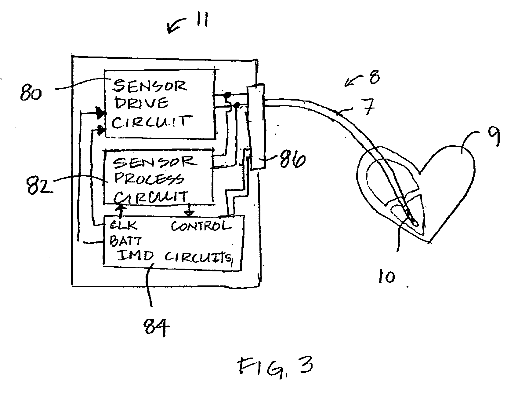
a technology of optical sensors and normalization methods, applied in the field can solve the problems of tissue encapsulation, capsules may become relatively thick, and one limitation encountered with the use of implantable optical sensors, and achieve the effect of accurately estimating blood oxygen saturation

Inactive Publication Date: 2007-03-15
MEDTRONIC INC
View PDF10 Cites 42 Cited by
  • Summary
  • Abstract
  • Description
  • Claims
  • Application Information

AI Technical Summary

Benefits of technology

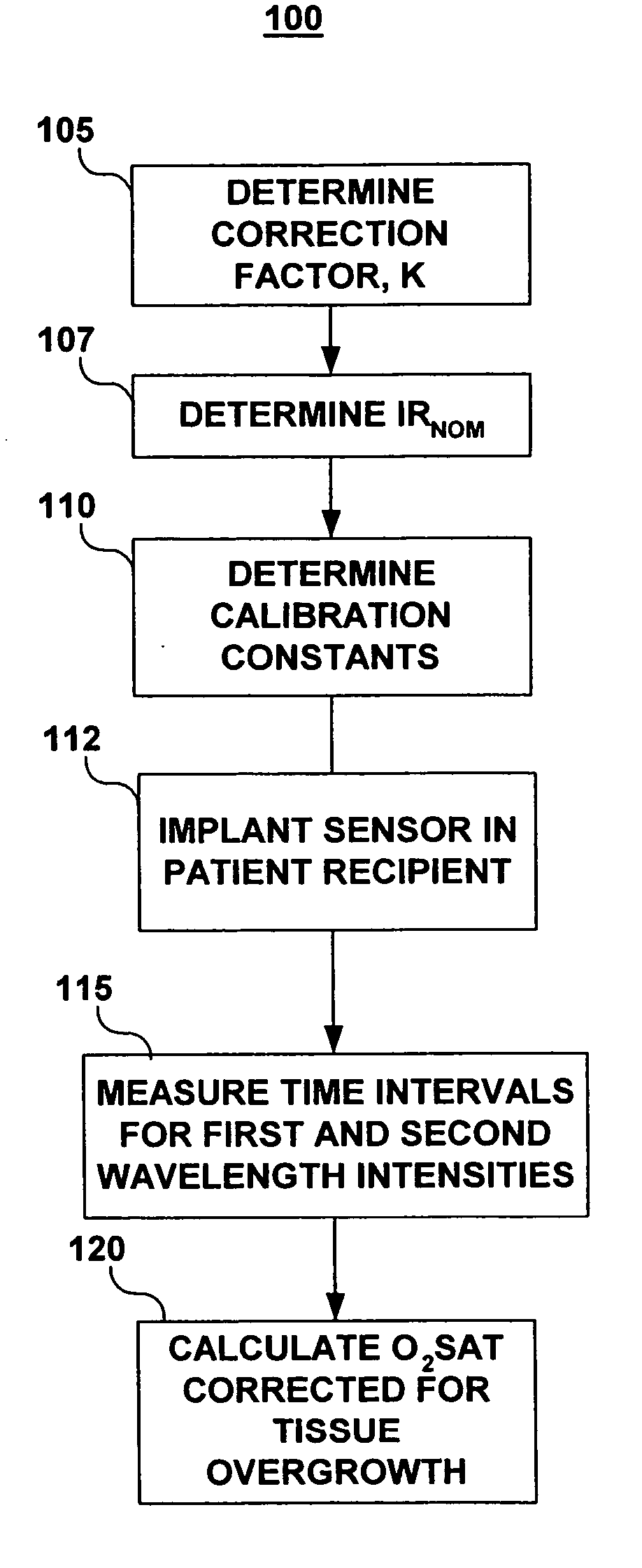
[0012] In an exemplary embodiment, an implantable optical sensor system and method are provided for accurately estimating blood oxygen saturation independent of the presence of tissue encapsulation of the optical sensor. According to the present invention, dual wavelength radiation is used to beneficially provide a first wavelength signal substantially independent of the presence of a metabolite and a second wavelength signal is substantially dependent upon the presence of said metabolite.

Problems solved by technology

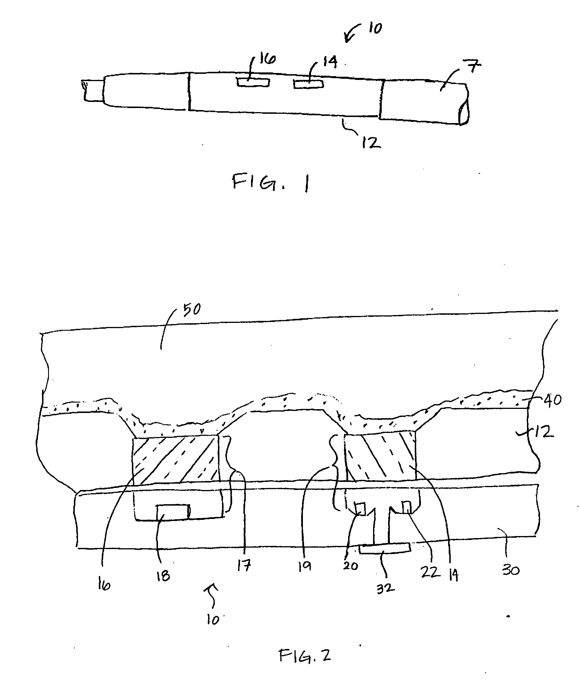
One limitation encountered with the use of implantable optical sensors can arise as the result of tissue encapsulation of the sensor that occurs as a result of the body's normal response to a foreign object.
If a blood oxygen sensor resides in an area of relatively low blood flow or a stagnant area, tissue encapsulation is likely to occur and the capsule may become relatively thick.
Such tissue overgrowth interferes with the performance of the sensor in accurately measuring blood oxygen or other metabolites by reducing the (light) signal to noise ratio.
Because the time course and occurrence of these events is unpredictable, the reliability of blood oxygen saturation measurements at any point in time may be uncertain.

Method used


Image

  • Normalization method for a chronically implanted optical sensor
  • Normalization method for a chronically implanted optical sensor
  • Normalization method for a chronically implanted optical sensor

Examples


Embodiment Construction

[0021] The present invention is directed at providing a method for accurately measuring changes in blood oxygen saturation using a chronically implantable optical sensor. In particular, the present invention provides a method for compensating for extra light intensity detected by the optical sensor due to light scattering matter, typically collagenous tissue or thrombus, which may be present over the sensor. The methods included in the present invention employ a two-wavelength system and a correction method that allows the extra light intensity due to light scattering tissue over the sensor to be compensated for in calculating oxygen saturation.

[0022] Two-wavelength optical sensing systems are known for use in the field of blood oximetry. See for example, U.S. Pat. No. 3,847,483 issued to Shaw et al. In a two-wavelength system, the reflected light signal of one wavelength that changes in intensity with blood oxygen saturation is normalized by a second wavelength of which the reflec...


PUM


Abstract

A system and method are provided for estimating blood oxygen saturation independent of optical sensor encapsulation due to placement in blood, where the blood includes a blood flow characteristic of: a relatively low, a stasis, a stagnant value. The method includes determining tissue overgrowth correction factor that includes optical properties of the tissue that cause scattering of the emitted light to a detector and relative amplitudes of the emitted light wavelengths. A corrected time interval measured for infrared light is based on an infrared signal and a corrected time interval for red light is determined by subtracting red light signal due to presence of tissue overgrowth. The red light signal due to tissue overgrowth is proportional to total infrared signal less nominal infrared signal. Oxygen saturation is estimated based on standard calibration factors and the ratio of the corrected infrared time interval and the corrected red time interval.

Description

FIELD OF THE INVENTION [0001] The present invention relates generally to the field of implantable optical sensors and more specifically to a method for providing accurate optical sensing of blood oxygen saturation in the presence of tissue overgrowth on the optical sensor. BACKGROUND OF THE INVENTION [0002] Implantable medical devices (IMDs) for monitoring a physiological condition or delivering a therapy typically rely on one or more sensors positioned in a patient's blood vessel, heart chamber, or other portion of the body. Examples of IMDS include heart monitors, pacemakers, implantable cardioverter-defibrillators (ICDs), myostimulators, nerve stimulators, drug delivery devices, and other IMDs where such sensors are desirable. Implantable sensors used in conjunction with an IMD generally provide a signal related to a physiological condition from which a patient condition or the need for a therapy can be assessed. [0003] Measurement of blood oxygen saturation levels are of interes...

Claims


Application Information

Patent Timeline
IPC IPC(8): A61B5/00
CPCA61B5/1459
Inventor ROBERTS, JONATHAN P.
Owner MEDTRONIC INC
Learn More