
Optical network regenerator bypass module and associated method

Inactive Publication Date: 2007-03-15
ALCATEL LUCENT SAS
View PDF6 Cites 11 Cited by
  • Summary
  • Abstract
  • Description
  • Claims
  • Application Information

AI Technical Summary

Benefits of technology

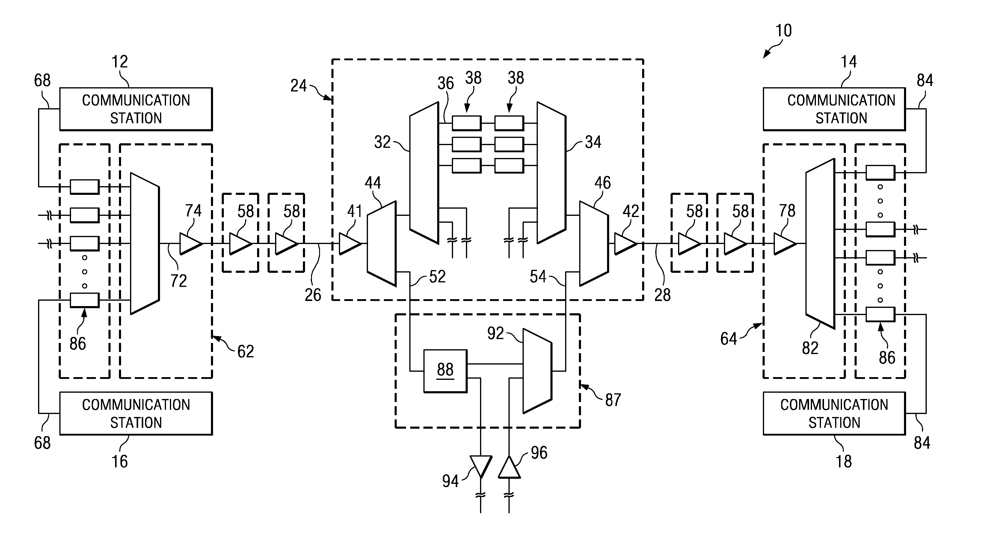
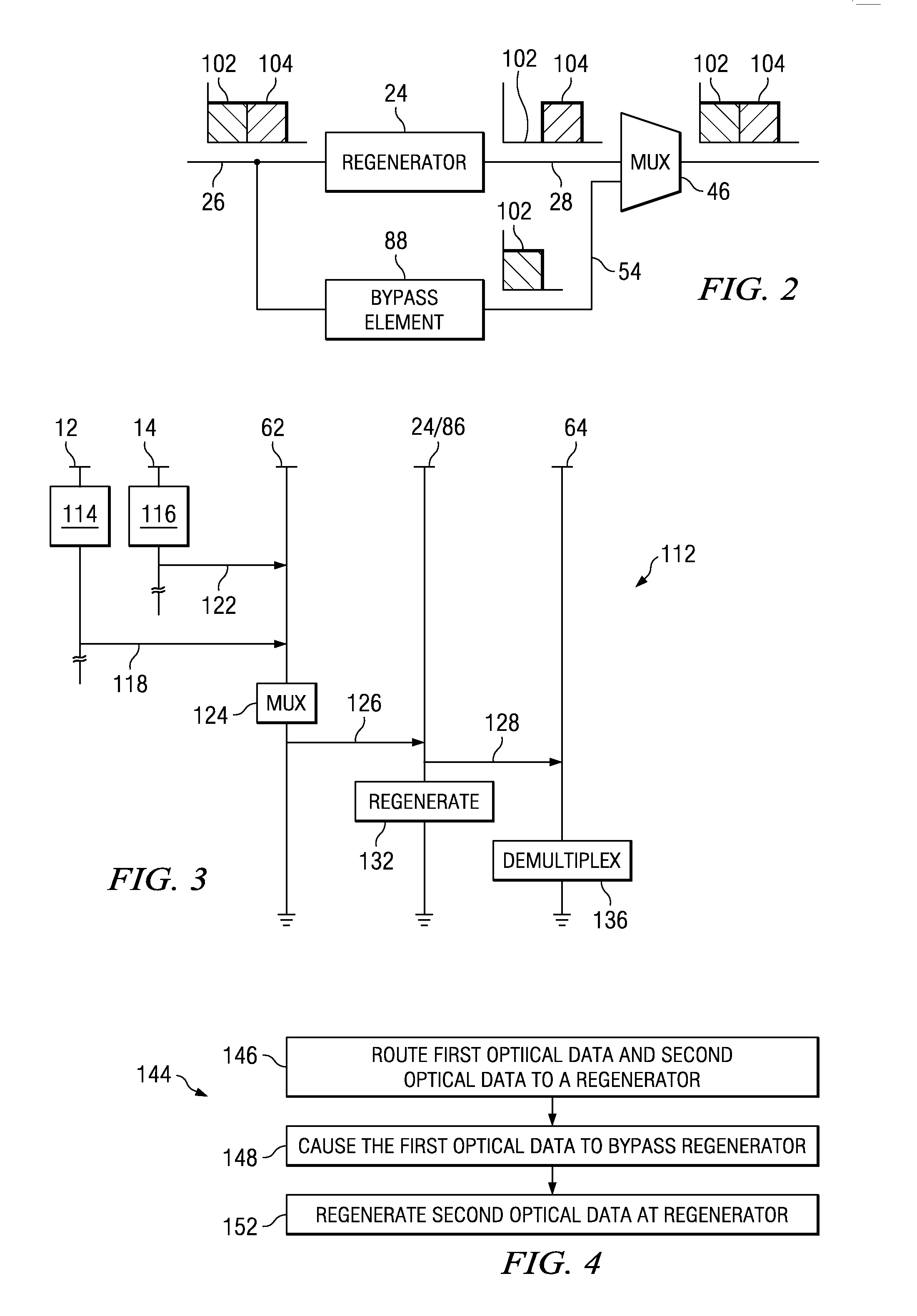
[0014] In another aspect of the present invention, an optical bypass is positioned, in-line with a fiber upon which first optical data and second optical data is transported. The optical bypass element is further positioned in parallel with an optical regenerator. The optical bypass element forms, for instance, an optical interleaver that passes optical data of first wavelengths. When the first optical data, communicated by way of a new optical network portion, is modulated to be of the first wavelengths, the optical data, when delivered to the regenerator, bypasses the regenerator as the optical interleaver permits the optical data to pass there through. When the second optical data, communicated by way of the legacy network part, is modulated to be of the second wavelength, the data, when delivered to the regenerator, is regenerated at the regenerator. Through appropriate selection of the characteristics of the optical interleaver and appropriate modulation of the optical data transported by way of the separate network parts, optical data needing to be regenerated is regenerated, and optical data that does not necessitate regeneration is bypassed around the regenerator. Unnecessary regeneration of optical data is thereby avoided while also permitting optical data that requires regeneration to be regenerated by the regenerator.

Problems solved by technology

Examples of transmission impairments which might result in the quality of the received signal being impacted are signal to noise ratio, chromatic dispersion, polarization mode dispersion and self phase modulation.
Regeneration of optical data not necessitating regeneration entails needless expense in furnishing the O-E-O regeneration converters at the regenerator site.

Method used


Image

  • Optical network regenerator bypass module and associated method
  • Optical network regenerator bypass module and associated method
  • Optical network regenerator bypass module and associated method

Examples


Embodiment Construction

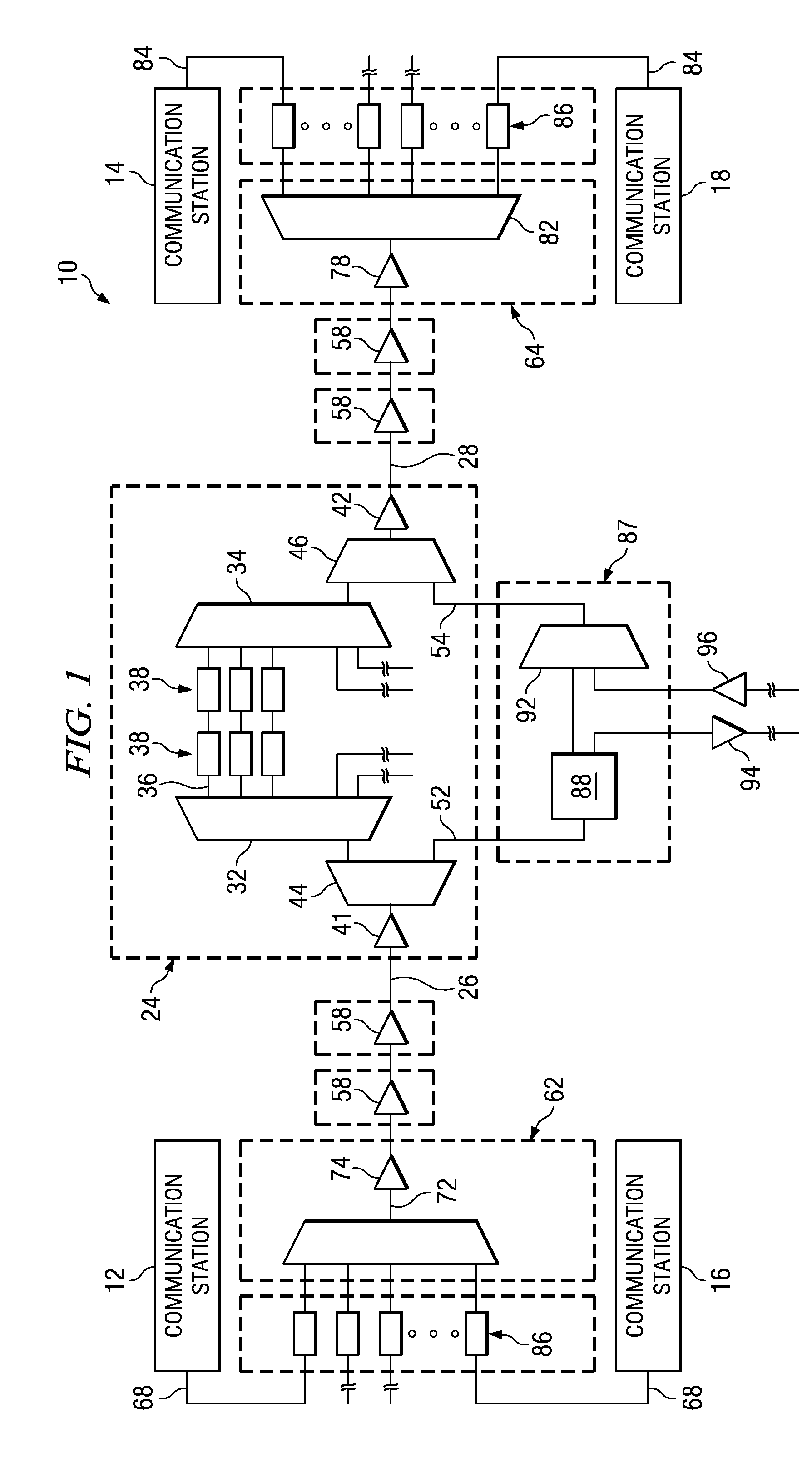
[0024] Referring first to FIG. 1, an optical communication system, shown generally at 10, provides for the communication of data between line terminating equipment, here represented by, and described in terms of sets of, communication stations forming communication endpoints. Here, two sets of communication stations forming communication endpoints are shown. The communication stations 12 and 14 form a communication station pair between which first optical data is communicated, and the communication stations 16 and 18 are representative of a second pair of communication stations between which second optical data is communicated. The sets formed of the communication stations 12-14 and 16-18 are merely exemplary. Other numbers of, and other combinations of, communication stations are capable of forming communication endpoints between which data is communicated pursuant to operation of the communication system.

[0025] Here, the communication system includes both a legacy network portion...


PUM


Abstract

An optical bypass element for an optical communication system. The optical bypass element, formed of an optical interleaver, is positioned in parallel with a regenerator. Data requiring regeneration is caused to be provided to the regenerator while data not requiring regeneration is bypassed about the regenerator by way of the optical bypass element. Once bypassed around the regenerator and once regenerated at the regenerator, the respective data is recombined and subsequently routed to communication endpoints.

Description

CROSS-REFERENCE TO RELATED APPLICATIONS [0001] The present invention claims the priority of Provisional Patent Application No. 60 / 715,427, filed on Sep. 9, 2005, the contents of which are incorporated herein by reference.[0002] The present invention relates generally to an optical communication system in which wavelength division multiplexed (WDM) data is communicated. More particularly, the present invention relates to apparatus, and an associated method, that provides routing of first optical data of the WDM data around a regenerator, while permitting second optical data of the WDM data to be applied to the regenerator. [0003] An optical communication system is formed with line terminating equipment within which Electrical-Optical (E-O) and Optical-Electrical (O-E) having two or more different transmission performance characteristics are deployed. Viz., the system includes a network part that requires optical data to be communicated with relatively low transmission impairments and...

Claims


Application Information

Patent Timeline
IPC IPC(8): H04B10/00H04B10/29
CPCH04J14/02H04B10/29H04J14/0307
Inventor BUTLER, DAVID
Owner ALCATEL LUCENT SAS
Learn More