Piston assembly of cooler
a cooler and assembly technology, applied in the direction of piston pumps, magnetic circuit rotating parts, magnetic circuit shape/form/construction, etc., can solve the problems of reducing operational efficiency and production yield, difficult to fix the nuts, and inconvenient and time-consuming coupling methods as above, so as to save production costs, improve productivity, and reduce the time for coupling and assembly
- Summary
- Abstract
- Description
- Claims
- Application Information
AI Technical Summary
Benefits of technology
Problems solved by technology
Method used
Image
Examples
first embodiment
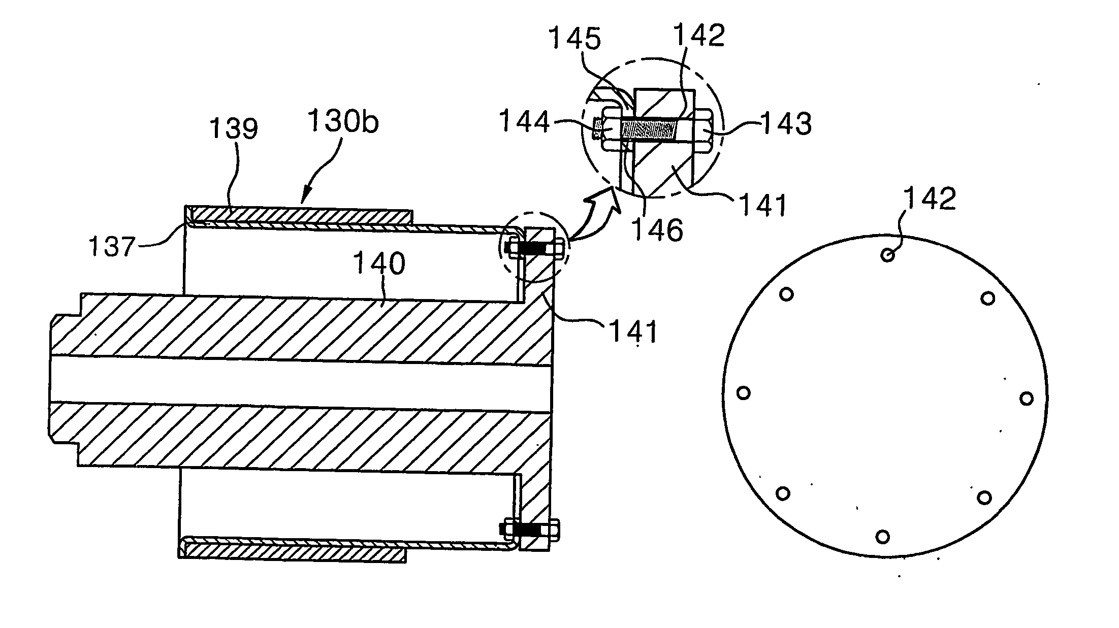
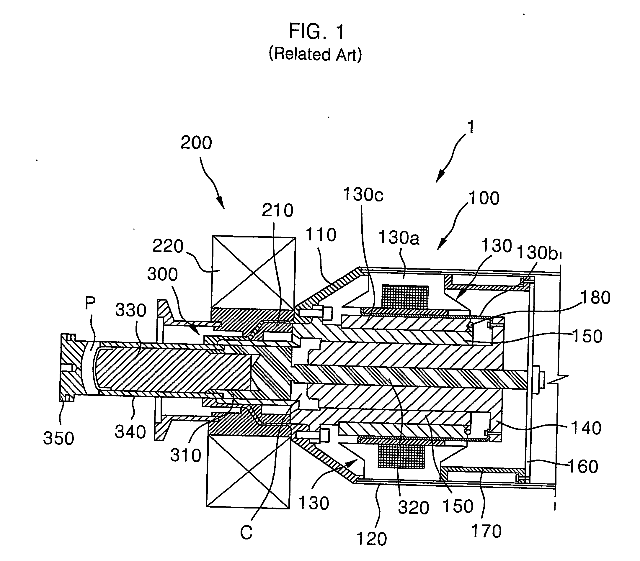
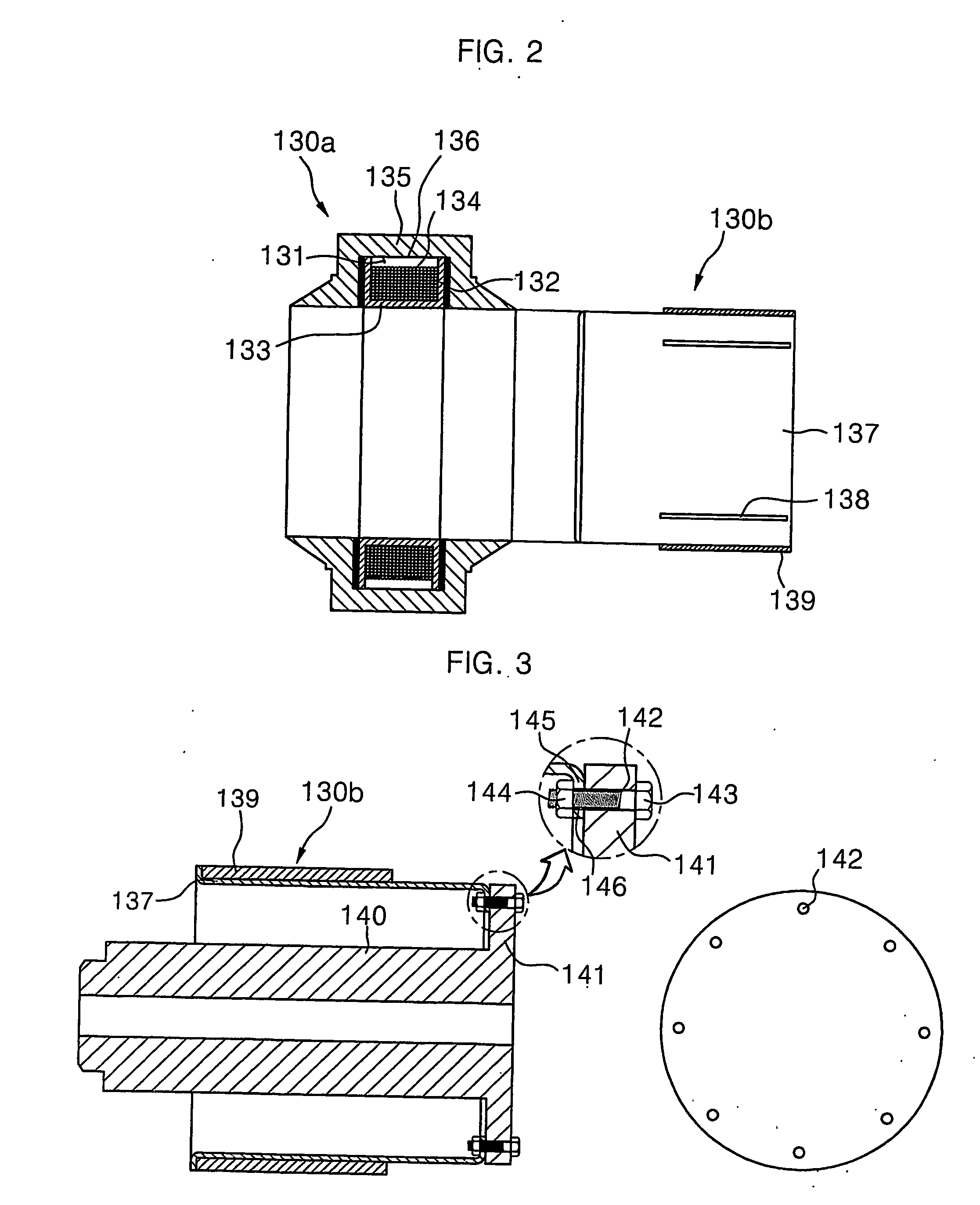
[0049] A piston assembly 400 according to the present invention includes a hollow cylinder-shaped magnet sleeve 420 formed at a thickness, and having a plurality of magnets 410, each magnet having a predetermined size, bonded on its external circumferential surface; a hollow cylinder-shaped piston 430 inserted into the hollow space of the magnet sleeve 420; and a hollow disc-shaped ring 440 made of stainless steel, and forcibly fixed to the piston 430 by a shrink fitting process to be located between the magnet sleeve 420 and the piston 430. The ring 440 is welded to the magnet sleeve 420, which is made of the same material as the ring 440, so as to obtain the configuration of the piston assembly by coupling the magnet sleeve 420 and the piston 430. Non-described reference numeral 470 in the drawing is indicative of a welding portion.
[0050] Now hereinafter, the piston assembly 400 according to a first embodiment of the present invention is described in detail.
[0051] In the case of ...
second embodiment
[0064] The piston assembly 600 according to the present invention includes a hollow cylinder-shaped magnet sleeve 620 having a bent portion 680 inwardly bent on one end of the cylinder and from which a bolt insertion hole formed in the bent portion 680 is removed so that the bent portion 680 of the magnet sleeve 620 is fixed to the flange part 640 of the piston 630 by the fusion-fixing of a fixing member 670 by an applied electric current; the fixing member 670 fusion-fixed to the magnet sleeve 620 by applied electric current, and functioning as a solvent to fix the bent portion 680 of the magnet sleeve 620 and the flange part 640 of the piston 630; and a piston 630 having a plurality of fixing member-inserting holes 660 formed on the flange part 640 of the piston 630, in which a fixing member 670 is contacted with the bent portion 680 of the magnet sleeve 620 when the fixing member 670 is inserted therethrough, and the fixing member 670 is fused by applied electric current, and fix...
third embodiment
[0073]FIG. 8 is a coupling sectional view of the piston assembly 800 according to the present invention.
[0074] Referring to FIG. 8, the piston assembly 800 of a third embodiment of the present invention includes: a hollow cylinder-shaped magnet sleeve 820 having a bent portion 880 inwardly bent on one end of the cylinder, and a plurality of fixing member-inserting holes 860b on the bent portion 880 so that the bent portion 880 of the magnet sleeve 820 is fixed to the flange part 840 of the piston 830 by the fusion-fixing of a fixing member 870 by applied electric current; the fixing member 870 fusion-fixed to the magnet sleeve 820 by applied electric current, and functioning as a solvent to fix the bent portion 880 of the magnet sleeve 820 and the flange part 840 of the piston 830; and a piston 830 having a plurality of fixing member-inserting holes 860a formed on the flange part 840 of the piston 830, in which a fixing member 870 is contacted with the fixing member-inserting hole 8...
PUM
 Abstract
Description
Claims
Application Information
 - R&D
- Intellectual Property
- Life Sciences
- Materials
- Tech Scout
- Unparalleled Data Quality
- Higher Quality Content
- 60% Fewer Hallucinations
Browse by: Latest US Patents, China's latest patents, Technical Efficacy Thesaurus, Application Domain, Technology Topic, Popular Technical Reports.
© 2025 PatSnap. All rights reserved.Legal|Privacy policy|Modern Slavery Act Transparency Statement|Sitemap|About US| Contact US: help@patsnap.com


