
Infra-red thermal imaging of laser welded battery module enclosure components

a battery module and enclosure technology, applied in the field of infrared thermal imaging of thermoplastic components used in battery module enclosures, can solve the problems of inability to detect internal leakage or weak welds that are not visible, and the use of battery modules is often used,

Inactive Publication Date: 2007-03-01
BATTERY PATENT TRUST
View PDF10 Cites 19 Cited by
  • Summary
  • Abstract
  • Description
  • Claims
  • Application Information

AI Technical Summary

Benefits of technology

"The present invention is a thermal imaging system for inspecting the quality of a weld formed between two battery module enclosure components. The system includes a thermal imaging camera that captures a thermal signature of the weld and an image processing module that compares the thermal signature to a template signature to verify the structural integrity of the weld. The system can detect any deviation in the weld and generate weld integrity statistics based on the inspected welds. The technical effect of the invention is to provide a non-destructive and efficient method for inspecting the quality of battery module enclosure welds, which can improve the overall manufacturing process of battery modules for electric vehicles."

Problems solved by technology

Additionally, the battery modules are often utilized in physically unstable environments such as vehicles for hybrid electric applications.
However, variation among plastic components used to make the battery module enclosures creates the possibility of weak or even non-existent welds at defective regions.
However, external inspection of battery module enclosures cannot identify internal leakage or weak welds that are not visibly apparent.
Additionally, it is costly and time consuming to manually inspect every weld of every plastic enclosure component that is manufactured.

Method used


Image

  • Infra-red thermal imaging of laser welded battery module enclosure components
  • Infra-red thermal imaging of laser welded battery module enclosure components
  • Infra-red thermal imaging of laser welded battery module enclosure components

Examples


Embodiment Construction

[0019] The following description of the preferred embodiment(s) is merely exemplary in nature and is in no way intended to limit the invention, its application, or uses. For purposes of clarity, the same reference numbers will be used in the drawings to identify similar elements. As used herein, the term module refers to an application specific integrated circuit (ASIC), an electronic circuit, a processor (shared, dedicated, or group) and memory that execute one or more software or firmware programs, a combinational logic circuit, and / or other suitable components that provide the described functionality.

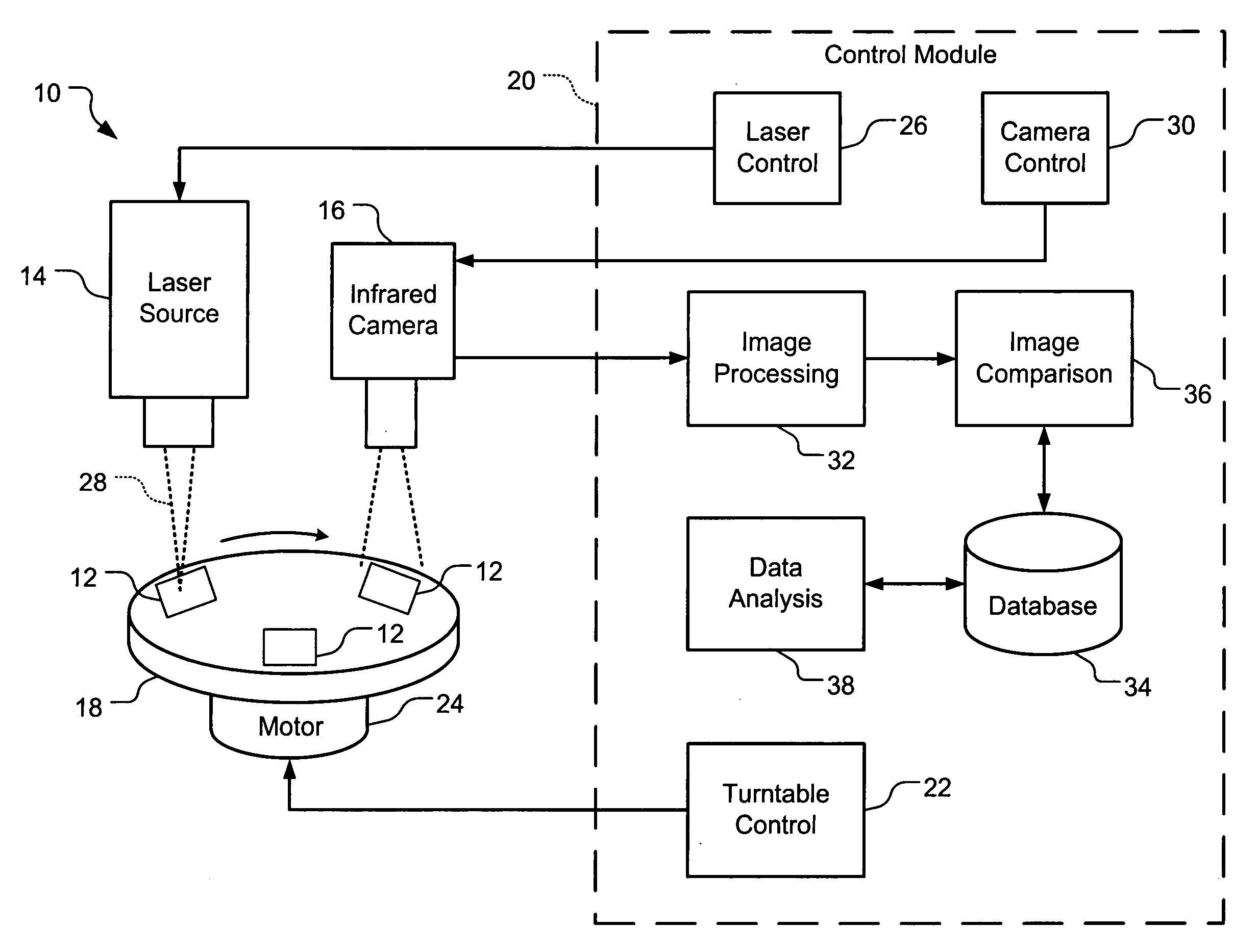
[0020] Referring now to FIG. 1, an exemplary thermal imaging system 10 for a battery module enclosure 12 includes a laser source 14, an infra-red thermal imaging camera 16, and a turntable 18. Plastic enclosure components 12 that are desired for welding are fixed to the turntable 18. For example, the turntable 18 may move the plastic enclosure components 12 between three different p...


PUM

PropertyMeasurementUnit
wavelengthsaaaaaaaaaa
thermal imaging cameraaaaaaaaaaa

Abstract

A thermal imaging system for a battery module enclosure that includes first and second battery module enclosure components between which a weld is formed includes a thermal imaging camera that focuses on the first and second battery module enclosure components within a predetermined amount of time after the weld is formed and that acquires a thermal signature. A control module includes an image processing module that receives the thermal signature and that locates a predetermined reference point in the thermal signature. An image comparison module receives the thermal signature and uses the predetermined reference point to compare the thermal signature to a template signature in order to verify structural integrity of the weld. The image comparison module computes a relative measure of deviation of the thermal signature from the template signature and identifies the weld as defective when the relative measure of deviation is greater than a predetermined value.

Description

FIELD OF THE INVENTION [0001] The present invention relates to thermal imaging of plastic welds, and more particularly to infra-red thermal imaging of thermoplastic components used in battery module enclosures. BACKGROUND OF THE INVENTION [0002] Battery module enclosures house one or more battery cells that are utilized to provide electrical power. For example, a battery module enclosure may include multiple battery cells connected in series to provide a desired voltage. In some cases, the battery cells comprise liquid materials such as potassium hydroxide and require airtight sealing from an exterior of the battery module as well as between individual cells to prevent a short-circuit condition. Additionally, the battery modules are often utilized in physically unstable environments such as vehicles for hybrid electric applications. Therefore, battery module enclosures commonly comprise thermoplastic materials such as polymeric blends. Since the battery module enclosures typically i...

Claims


Application Information

Patent Timeline
Patent Type & Authority Applications(United States)
IPC IPC(8): G06K9/00B23K31/12
CPCB23K31/12B29C66/9672G01N25/72B29C65/8261G01N33/442B29C65/8253B29C65/00B29L2031/7146B29C65/1635B29C65/1664B29C66/1122B29C66/1142B29C66/5344B29C66/542B29C66/73921B29C66/952B29C66/612B29C65/7882
Inventor ANANTHARAMAN, SATISH
Owner BATTERY PATENT TRUST
Learn More