
Collision object discrimination apparatus for vehicle

a technology for discriminating apparatuses and collision objects, applied in the direction of bumpers, vehicle components, pedestrian/occupant safety arrangements, etc., can solve the problem of not largely increasing the size of the bumper, and achieve the effect of reducing the design change around the bumper and not largely increasing the bumper siz

Inactive Publication Date: 2007-03-01
DENSO CORP
View PDF14 Cites 36 Cited by
  • Summary
  • Abstract
  • Description
  • Claims
  • Application Information

AI Technical Summary

Benefits of technology

[0012] The present invention is made in view of the foregoing matter, and it is an object of the present invention to provide a collision object discrimination apparatus for a vehicle, capable of reducing a large increase in a mounting space for a load detection unit in a bumper.
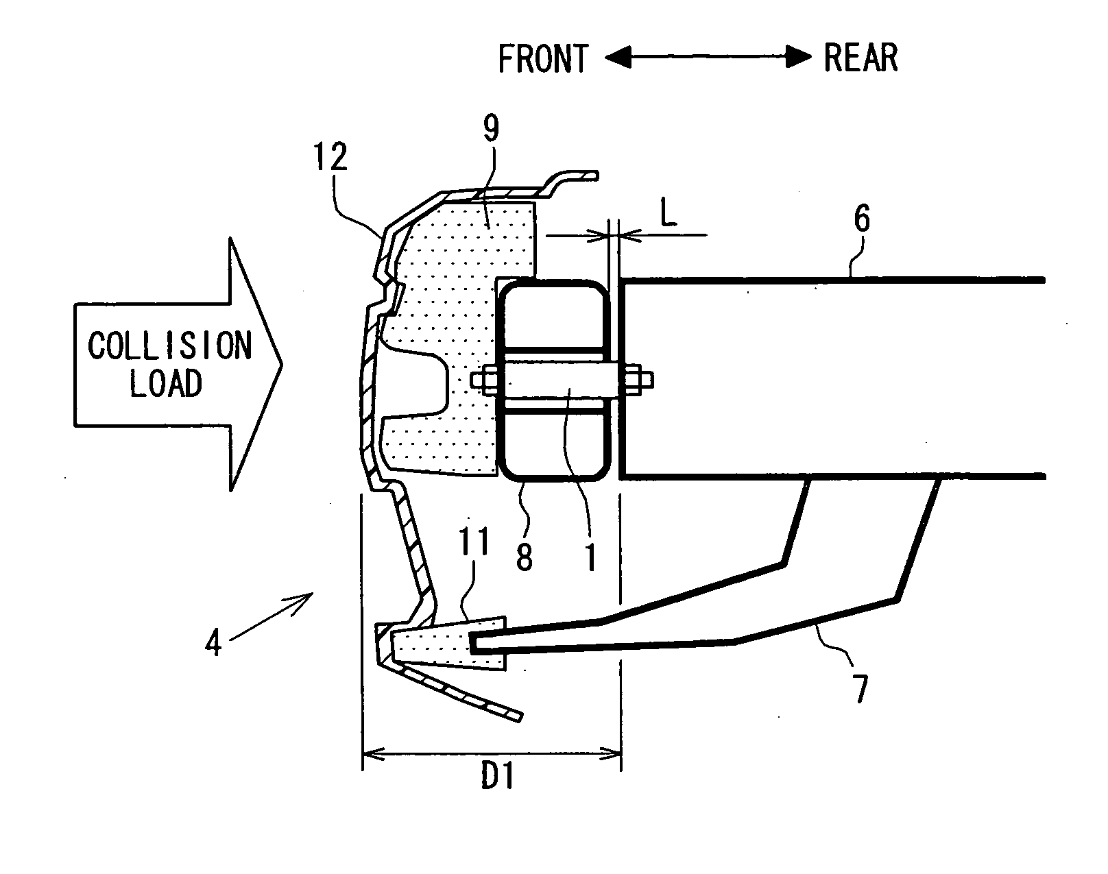
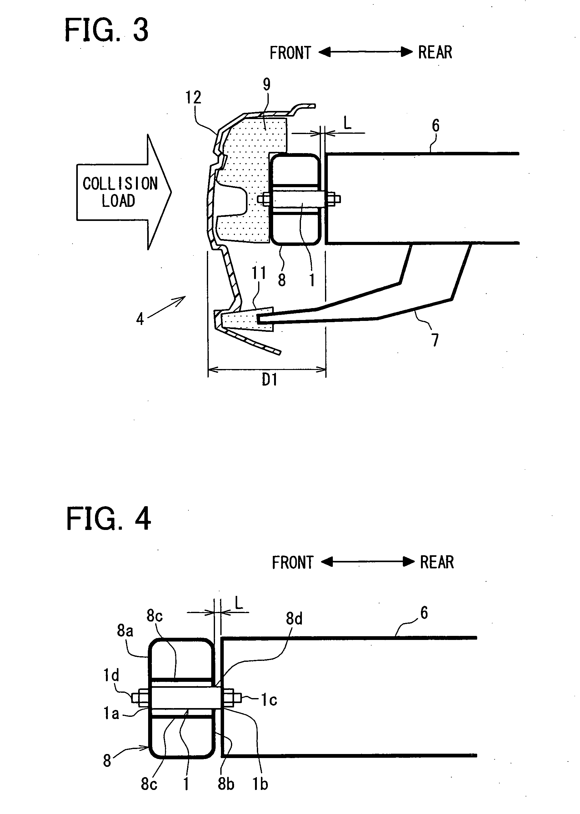
[0015] According to the above structure, at least a part of the load detection unit is located inside of the bumper reinforcement member. Namely, the above structure does not require a large space for mounting the load detection unit. Therefore, even when the load detection unit is mounted in the bumper, a size of the bumper is not largely increased as compared to that of the bumper without mounting the load detection unit. Furthermore, a design change around the bumper is reduced.

Problems solved by technology

Therefore, even when the load detection unit is mounted in the bumper, a size of the bumper is not largely increased as compared to that of the bumper without mounting the load detection unit.

Method used


Image

  • Collision object discrimination apparatus for vehicle
  • Collision object discrimination apparatus for vehicle
  • Collision object discrimination apparatus for vehicle

Examples


Embodiment Construction

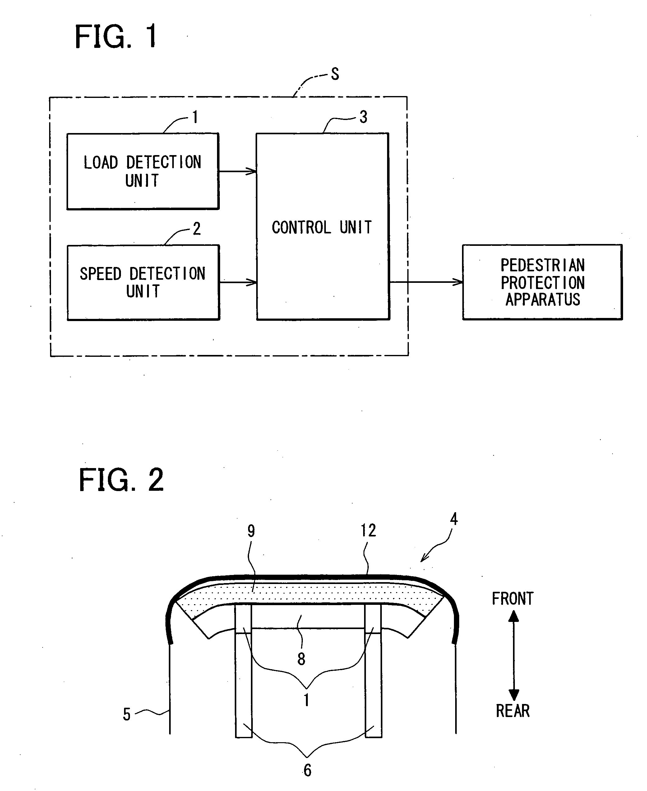
[0026] An example embodiment of a collision object discrimination apparatus of the present invention will now be described with reference to FIGS. 1 to 4. As shown in FIG. 1, the collision object discrimination apparatus S is mainly provided with a load detection unit 1, a vehicle speed detection unit 2 and a control unit 3 including a collision object discrimination circuit. The control unit 3 is connected to a pedestrian protection apparatus through a signal wire and the like. For example, the load detection unit 1 is constructed of at least one load sensor such as a strain-type load sensor, and the vehicle speed detection unit 2 is constructed of at least one speed sensor.

[0027] As shown in FIGS. 2 and 3, two side members 6 are provided in a substantially front part of a vehicle body 5, as support members. The side members 6 extend in a vehicle front and rear direction. Also, the side members 6 are spaced from each other in a vehicle right and left direction. For example, the lo...


PUM


Abstract

A collision object discrimination apparatus for a vehicle has a bumper absorber, a bumper reinforcement member, a support member, a load detection unit and a control unit for discriminating a sort of object colliding with a bumper based on a load detected by the load detection unit. The load detection unit has a first end and a second end opposite to teach other. The first end is connected to the bumper reinforcement member and the second end is connected to the support member. Further, the load detection unit is disposed such that at least a part of the load detection unit is located inside of the bumper reinforcement member.

Description

CROSS REFERENCE TO RELATED APPLICATION [0001] This application is based on Japanese Patent Application No. 2005-244364 filed on Aug. 25, 2005, the disclosure of which is incorporated herein by reference. FIELD OF THE INVENTION [0002] The present invention relates to a collision object discrimination apparatus for a vehicle for discriminating a sort of object colliding with the vehicle. The collision object discrimination apparatus is exemplary used to determine whether the object is a human such as a pedestrian. BACKGROUND OF THE INVENTION [0003] Various methods and devices for detecting a collision load applied to a vehicle due to a vehicle collision have been known. For example, in Japanese Patent Publication No. 2004-212281 (US2004 / 0129479A1), a wire having a predetermined initial tension is transversely stretched along the front surface of a bumper reinforcement member of the vehicle. A collision load applied to the vehicle is detected by measuring a change of tension of the wir...

Claims


Application Information

Patent Timeline
Patent Type & Authority Applications(United States)
IPC IPC(8): B60R19/02
CPCB60R19/483B60R21/34B60R21/0136
Inventor TANABE, TAKATOSHI
Owner DENSO CORP
Learn More