Hole punch element
- Summary
- Abstract
- Description
- Claims
- Application Information
AI Technical Summary
Benefits of technology
Problems solved by technology
Method used
Image
Examples
Embodiment Construction
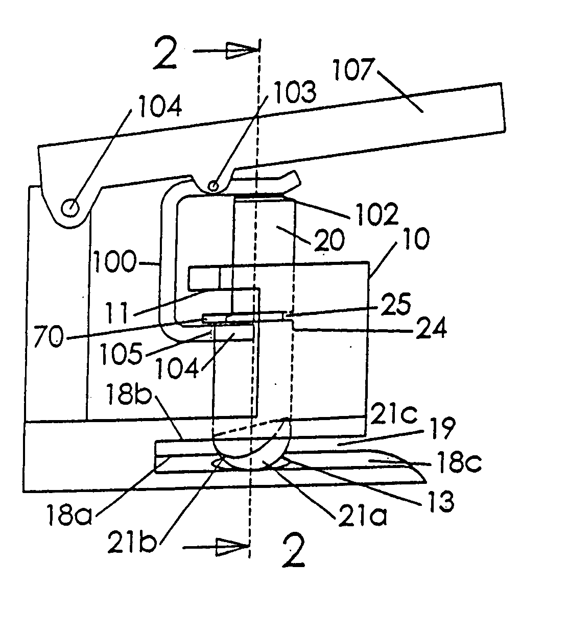
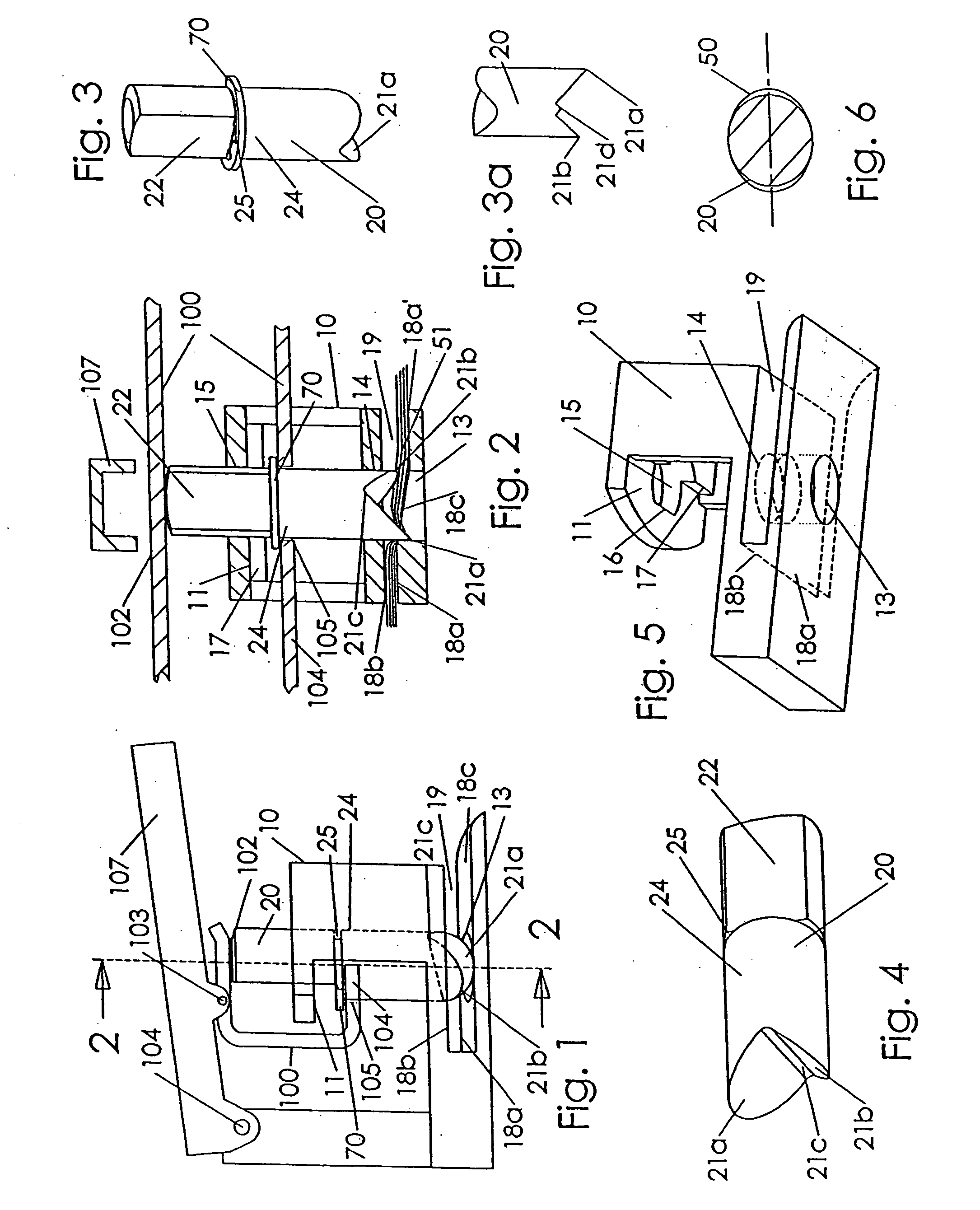
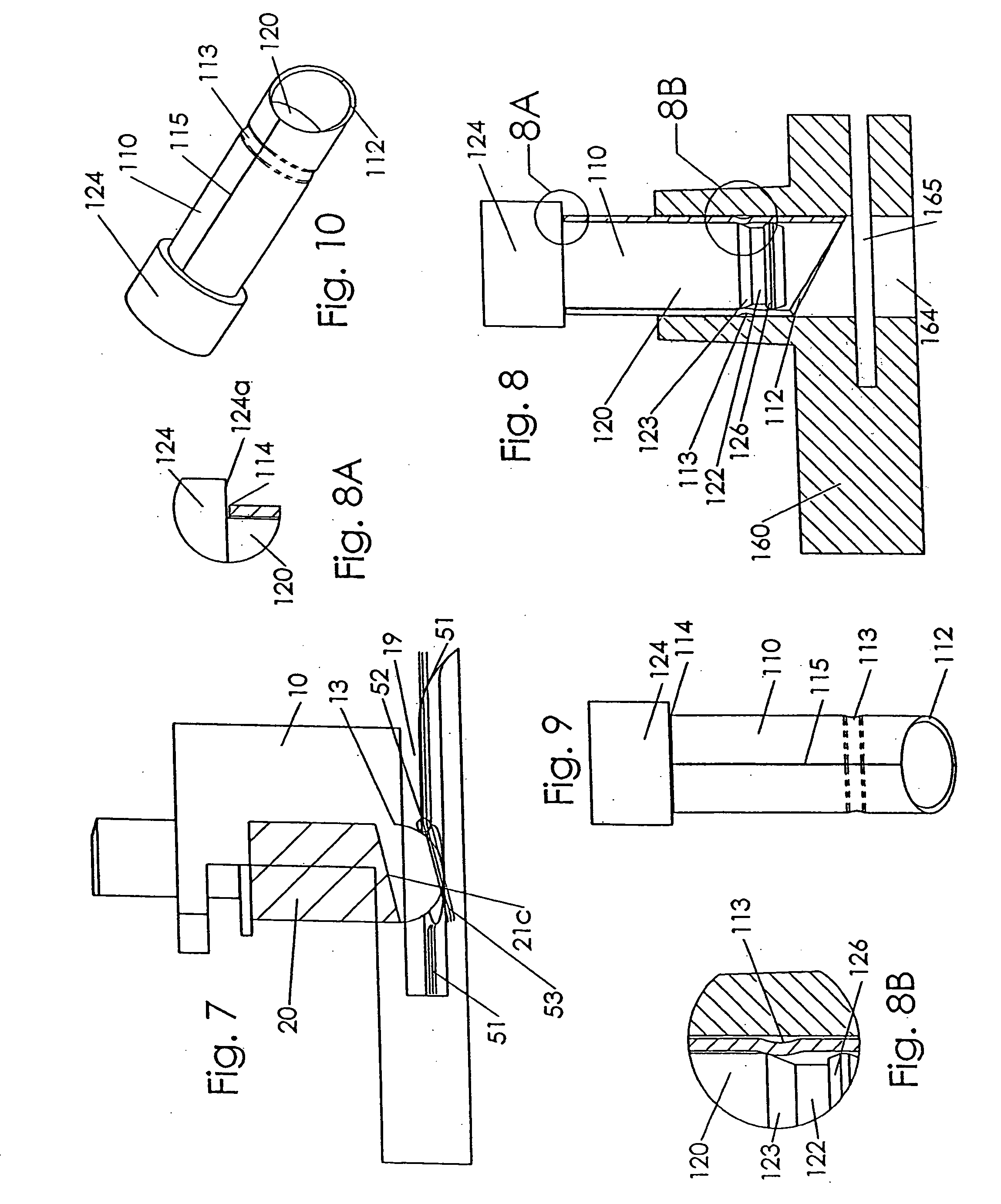
[0035] The present invention is directed to a hole punch element. A hole punch element may be defined as the punch pin, or as the structure within the immediate region of the hole punch device near the pin including the structures that guide the pin and the sheet media or substrate to be punched, such as a stack of papers. For example, a die cast punch support structure may guide pins as well as support an operating handle.
[0036] FIGS. 1 to 7 show one exemplary embodiment of an improved punch element. Pin 20 is vertically slidable and guided in frame 10 along a longitudinal pin axis, depicted as a vertical, dashed line. In FIG. 1, pin 20 is shown in an intermediate position between an uppermost position and a lowermost position. Lower cutting point 21a of pin 20 is just protruding into anvil cavity 13. Upper cutting point 21b of pin 20 has not entered cavity 13 in FIG. 1.
[0037] Tie bar 100 is linked to pin 20. Tie bar 100 is preferably a side facing “U” channel in the illustrated ...
PUM
| Property | Measurement | Unit |
|---|---|---|
| Length | aaaaa | aaaaa |
| Height | aaaaa | aaaaa |
Abstract
Description
Claims
Application Information
 - R&D
- Intellectual Property
- Life Sciences
- Materials
- Tech Scout
- Unparalleled Data Quality
- Higher Quality Content
- 60% Fewer Hallucinations
Browse by: Latest US Patents, China's latest patents, Technical Efficacy Thesaurus, Application Domain, Technology Topic, Popular Technical Reports.
© 2025 PatSnap. All rights reserved.Legal|Privacy policy|Modern Slavery Act Transparency Statement|Sitemap|About US| Contact US: help@patsnap.com


